Transcription of ASTROAI USER MANUAL TRUE RMS DIGITAL MULTIMETER …
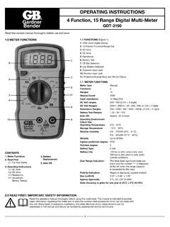
1 ASTROAI USER MANUAL TRUE RMS DIGITAL MULTIMETERT hank you for purchasing the True RMS 6000 Count DIGITAL MULTIMETER from ASTROAI . The ASTROAI True RMS DIGITAL MULTIMETER is designed to be safely and accurately used by professionals in a commercial setting or weekend DYer s that need a little more utility from their standard DIGITAL MULTIMETER . This MANUAL provides all safety information, operation instruction, specifications, and maintenance for the meter. The instrument performs AC/DC Voltage, AC/DC Current, Resistance, Audible continuity , Diode, hFE, Frequency, Capacitance, and Temperature Testing.
2 Thank you again for choosing ASTROAI , if you have any questions or concerns regarding your product, please contact us at Fully read and understand this MANUAL before using this DIGITAL MULTIMETER . WARNING: To avoid possible electric shock or personal injury, and to avoid possible damage to the Meter or to the equipment being tested, adhere to the following rules: Before using the Meter, inspect the exterior casing. Do not use the Meter if it is damaged or if all or part of the exterior casing is removed. Look for cracks or missing plastic. Pay special attention to the insulation around the connectors.
3 Inspect the test leads for damaged insulation or exposed metal. Check the test leads for continuity . Do not apply more than the rated voltage, as marked on the Meter, between the terminals or between any terminal and grounding. The MANUAL rotary switch should be placed in the correct position before measurement and should NOT be moved during measurement to prevent damage to the Meter. When the Meter is working at an effective voltage over 60V in DC or 30V rms in AC, special care should be taken because there is a danger of electric shock. Use the proper terminals, function, and range for your measurements.
4 Do not use or store the Meter in a high-temperature environment, do not expose to high levels of humidity, or near strong magnetic fields. The performance of the Meter may deteriorate after dampening. When using the test leads, keep your fingers behind the finger guards. Disconnect circuit power and discharge all high-voltage capacitors before testing resistance, continuity , diodes or hFE. Replace the battery as soon as the battery indicator appears. With a low battery, the Meter might produce false readings that can lead to electric shock and personal injury.
5 Remove the connection between the testing leads and the circuit being tested, and turn the Meter power off before opening the Meter case. When servicing the Meter, use only the same model number or identical electrical specifications replacement parts. The internal circuit of the Meter shall not be altered at will to avoid damage of the Meter and any accident. Clean using a soft cloth and mild detergent for the surface of the Meter. Do not use abrasive materials or solvents to prevent the surface of the Meter from corrosion and damage. Turn the Meter off when not in use and take out the battery when it is not going to be used for an extended period of time.
6 Regularly check the battery as it may leak when it has not been used for some time. Replace the battery as soon as leaking appears. A leaking battery will damage the SYMBOLS AC (Alternating Current)Low Battery DC (Direct Current)Diode AC and DCFuseEarth GroundContinuity TestDouble Insulated WarningAUTOAuto RangeDangerous Voltage may be presentComplies with EU directivesSPECIFICATIONSD igital Display5 , 5999 Sampling Speed2 times per secondLCD Size64 x 42mmRange SelectionAuto or ManualPolarity IndicationYesOverload IndicationYesLow Battery IndicationYesOperating Environment32 F~104 F (0 C~40 C); <80% RHStorage Temperature14 F~122 F (-10 C~50 C).
7 <85% RHPower1 x 9V 6F22 Battery IncludedDimensions190x90x35mmWeightApprox 357gTemperature TestYesTransistor TestYesDiode TestYesContinuity TestYesExternal Current TestYesCapacitanceYesFrequencyYesSafety/CompliancesEN 61010-1 CAT III 600V, CATII 1000 VDC Voltage600mV6 ( +5), V/60V/600V ( +3), 1000V (1%+5)AC Voltage600mV ( +8); 6V/60V/600V ( +6); 750V ( +8)Temperature-40 C~1370 C; -40 F~2000 F (1-5%+4 depending on temp)DC Current600 A/6000 A/60mA/600mA ( +5); 6A/10A ( +3)Transistor hFEPNP & NPN (lb 2 A; Vce 1V)Resistance600 /6K /60K /600K /6M ( +3); 60M ( +5)Capacitance60nF/600nF/6 F/60 F/600 F/60mFFrequency0~60 MHz (1%+5)Accuracy is guaranteed for 1 year when stored at 73 F 9 FMULTIMETER Function Terminal6.
8 A/mA SocketLCD SCREEN DIAGRAM%Duty Cycle FFahrenheit Temperature CCelsius TemperaturehFETransistor hFEContinuity TestDiode TestExternal Current Test (Clamp)AUTOA utorange ModeAPOA utomatic Power-OffData HoldMAXM aximum Reading MINM inimum ReadingDCACN egative ReadingLow Battery, Replace ImmediatelyRelative ModeGETTING TO KNOW YOUR DEVICES elect ButtonWhen using the rotary switch to select a MULTIMETER function, use the Select Button to further select the function. This applies only to multifunction settings like the temperature and test and backlight function button.
9 When taking a measurement, press this button to hold the data for easier recording. Press the button again to remove the hold function. Press and hold this button to turn on the backlight on the LCD ButtonWhen taking a measurement, press this button once to enter Max Mode . In this mode, the MULTIMETER will capture the highest reading it records. Press this button again to enter Min Mode which will capture the lowest reading it records. Press and hold this button to exit the Max/Min ButtonAC/DC Voltage, AC Current, and Resistance can all be measured in both Auto and MANUAL ranging.
10 The MULTIMETER will come set to Auto, but if you desire to select the range manually, press the Range Button repeatedly to find the desired range. Beware of selecting a range too low, as it will Overload the device and the MULTIMETER will not give a reading. Press and hold the Range Button to return back to Auto Ranging. Relative ButtonWhen taking measurements, you can utilize the Relative Button to get more accurate readings by removing the resistance of the test leads, for example. To activate this function, simply press the Relative Button. A small triangle (delta symbol) will appear on the display and the reading should change to zero.
