Transcription of ATC 100 E Series Porcelain High RF Power Multilayer Capacitors
1 ATC 100 E SeriesPorcelain High RF PowerMultilayer Capacitors Case E Size Capacitance Range (.380" x .380") 1 pF to 5100 pF High Q Ultra-Stable Performance Low ESR/ESL High RF Current/Voltage High RF Power High Reliability Extended WVDC Available with up to 7200 VDC Encapsulation Option*ATC, the industry leader, offers new improved ESR/ESL performancefor the 100 E Series RF Capacitors . This high Q Multilayer capacitoris ultra-stable under high RF current and voltage applications. Highdensity Porcelain construction provides a rugged, hermetic offers an encapsulation option for applications requiring ex-tended protection agains arc-over and functional applications: Bypass, Coupling, Tuning, Imped-ance Matching and DC circuit applications: HF/RF Power Amplifiers, Transmitters,Antenna Tuning, Plasma Chambers and Medical (MRI coils).
2 *For leaded styles onlyENVIRONMENTAL TESTSATC 100 E Series Capacitors are designed and manufactured tomeet and exceed the requirements of EIA-198, MIL-PRF-55681and SHOCK:MIL-STD-202, Method 107, Condition RESISTANCE:MIL-STD-202, Method VOLTAGE HUMIDITY:MIL-STD-202, Method 103, Condition A, with Volts DC ap-plied while subjected to an environment of 85 C with 85% rela-tive humidity for 240 hours TEST:MIL-STD-202, Method 108, for 2000 hours, at 125 of WVDC for Capacitors rated at 500 volts DC or of WVDC for Capacitors rated at 1250 volts DC or of WVDC for Capacitors rated above 1250 volts AND MECHANICALSPECIFICATIONSQUALITY FACTOR (Q):Greater than 10,000 (1 pF to 1000 pF) @ 1 than 10,000 (1100 pF to 5100 pF) @ 1 COEFFICIENT OF CAPACITANCE (TCC):+90 30 PPM/ C (-55 C to +125 C)INSULATION RESISTANCE (IR):1 pF to 5100 pF:105 Megohms min. @ +25 C at 500 min.
3 @ +125 C at 500 VOLTAGE (WVDC):See Capacitance Values Table, page WITHSTANDING VOLTAGE (DWV):250% of WVDC for Capacitors rated at 500 volts DC or less for 5 of WVDC for Capacitors rated at 1250 volts DC or less for 5 of WVDC for Capacitors rated above 1250 volts DC for 5 :Less than ( or pF), whichever is EFFECTS:NonePIEZOELECTRIC EFFECTS:None(No capacitance variation with voltage or pressure).CAPACITANCE DRIFT: ( or pF), whichever TEMPERATURE RANGE:From -55 C to +125 C (No derating of working voltage).TERMINATION STYLES:Available in various surface mount and leaded Mechanical Configurations, page STRENGTH:Terminations for chips and pelletswithstand a pull of 10 lbs. min., 25 lbs. typical, for 5 seconds indirection perpendicular to the termination surface of the capaci-tor. Test per MIL-STD-202, method # 001-809 Rev. M, 9/14 ATC 100 E Capacitance ValuesATC PART NUMBER CODE ATC100E 39 1 K W 3600 X C Series Case Size Capacitance Code: First 2 significant digits for capacitance.
4 R=Decimal Point Laser Marking Indicates number of zeros following digits WVDC of capacitance in picofarads except for decimal values. Termination Code Capacitance Tolerance Packaging C - ATC Matrix Tray (Standard) T - Tape and Reel, 250 pc. qty. I - Special Packaging. Consult FactoryThe above part number refers to a 100 E Series (case size E) 390 pF capacitor,K tolerance ( 10%), 3600 WVDC, with W termination (Tin/Lead, Solder Plated over Nickel Barrier), laser marking and additional information and catalogs contact your ATC representative or call direct at (+1-631) factory for additional performance accepts orders for our parts using designations withor without the ATC prefix.
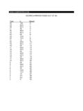
5 Both methods of defining the part number are equivalent, , part numbers referenced with the ATC prefix are interchangeable toparts referenced without the ATC prefix. Customers are free to use eitherin specifying or procuring parts from American Technical = X WVDC SPECIAL VALUES, TOLERANCES, MATCHING, AND CAPACITOR ASSEMBLIES ARE AVAILABLE. ATC S CUSTOM Power CAPACITOR ASSEMBLY CATALOG, ATC # 001-900 LISTSASSEMBLY OPTIONS. EXTENDED WORKING VOLTAGES ARE AVAILABLE FOR COMMERCIAL ORDERS ONLY. ENCAPSULATION OPTION AVAILABLE. PLEASE CONSULT FACTORY. CAPACITANCE TOLERANCECodeBCDFGJKMTol. pF pF pF 1% 2% 5% 10% 20% (pF) WVDCSTD. (pF) WVDCSTD. (pF) WVDCSTD. (pF) WVDCSTD. , , CDF, G, JK, M360072004705105606206807508209101011111 2113115116118120122124127130133136147515 6626875829110011012013015016018020022024 0270300330360F, G, J,K, M360072005000N/A391431471511561621681751 8219111021121221521822222723023323924725 1239043047051056062068075082091010001100 1200150018002200270030003300390047005100 F, G, J,K, MG, J,K, M360025001000500N/AEXTENDED VOLTAGEEXTENDED VOLTAGEEXTENDED VOLTAGEEXTENDED VOLTAGEEXTENDED VOLTAGEEXT.
6 TECHNICAL North lead styles and lengths are available; consult factory. All leads are high purity silver attached with high temperature solder and are 100 E Capacitors : Mechanical Configurations3 ATCSERIES& SIZE& TYPECASE SIZE& TYPEOUTLINESW/T IS ATERMINATION SURFACEBODY DIMENSIONSINCHES (mm)LEAD AND TERMINATIONDIMENSIONS AND MATERIALSLENGTH(L)WIDTH(W)THICKNESS(T)OV ERLAP(Y)MATERIALS100 EWE Solder +.015 ( + ).380 .010( ).170 ( ) ( ) , Solder Plated overNickel Barrier +.040 ( + )Heavy Tin/Lead Coated,over Nickel Barrier Termination100 ETE Solderable +.015 ( + )RoHS CompliantTin Plated overNickel Barrier Termination100 ECAE Gold +.015 ( + )RoHS CompliantGold Plated overNickel Barrier +.035 ( + )N/AHigh PuritySilver LeadsLL= .750 ( ) .350 .010( )TL= .010 .005( )Leads are Attached withHigh Temperature RibbonLTLLWLTLW100 EAWEA xial WireSilver-plated Copper LeadsDia.
7 = .032 .002(.813 .051)LL= ( ) WireSilver-plated Copper LeadsDia. = .032 .002(.813 .051)LL= ( ) TECHNICAL North 100 E Capacitors : Non-Magnetic Mechanical ConfigurationsCustom lead styles and lengths are available; consult factory. All leads are high purity silver attached with high temperature solder and are SizeNormalHigh MountHorizontal MountCase EVerticalElectrode OrientationHorizontalElectrode OrientationBACDB391K391 KWTWLLTS uggested Mounting Pad DimensionsATCSERIES& SIZE& TYPEOUTLINESW/T IS ATERMINATION SURFACEBODY DIMENSIONSINCHES (mm)LEAD AND TERMINATIONDIMENSIONS AND MATERIALSLENGTH(L)WIDTH(W)THICKNESS(T)OV ERLAP(Y)MATERIALS100 EWNE Non-MagSolder +.015 ( + ).380+.015 ( + ).170 ( ) ( ) , Solder Plated overNon-Magnetic BarrierTermination100 EPNE +.040 ( + )Heavy Tin/Lead Coated, overNon-Magnetic BarrierTermination100 ETNE Non-MagSolderable +.
8 015 ( + )RoHS CompliantTin Plated overNon-Magnetic Barrier Termination100 EMNEE +.035 ( + PuritySilver LeadsLL= .750 ( ) .350 .010( )TL= .010 .005( )Leads are Attached withHigh Temperature RibbonLTLLWLTLW100 EBNENon-MagAxial WireSilver-plated Copper LeadsDia. = .032 .002(.813 .051)LL= ( ) WireSilver-plated Copper LeadsDia. = .032 .002(.813 .051)LL= ( ) minAMERICAN TECHNICAL North are in 100 E Performance Data 30 MHz(Ty p i c a l ) E 1001000100001000001101001000C 30 MHz(Typical) 30 MHz(Typical) 101001000100100010000C 30 MHz(Typical) ESR VS. CAPACITANCEATC Series 100, CASE EQ VS. CAPACITANCEATC Series 100, CASE ECAPACITANCE (pF)( pF to 400 pF)CAPACITANCE (pF)( pF to 400 pF)ESR (Ohms)QESR VS. CAPACITANCEATC Series 100, CASE EQ VS. CAPACITANCEATC Series 100, CASE ECAPACITANCE (pF)(430 pF to 5100 pF) CAPACITANCE (pF)(430 pF to 5100 pF) ESR (Ohms)Q5 AMERICAN TECHNICAL North 100 E Performance Data 10 MHz2 MHzDotted line = Power dissipation limitedSolid line = Voltage limited (Vrms)The current rating is based on a 65 C mountingsurface and a device thermal resistance of12 C/W.)
9 A Power dissipation of 5W will resultin a case temperature of 125 C. 110100100100010000C 10 MHz30 MHz2 MHzDotted line = Power dissipation limitedSolid line = Voltage limited (Vrms)The current rating is based on a 65 C mountingsurface and a device thermal resistance of12 C/W. A Power dissipation of 5W will resultin a case temperature of 125 C. 10 MHz30 MHz2 MHzThe current rating is based on a 65 C mountingsurface and a device thermal resistance of12 C/W. A Power dissipation of 5W will resultin a case temperature of 125 line = Power dissipation limitedSolid line = Voltage limited (Vrms) 1010010000000110100100010000C (Ty p i c a l ) TC= +90 30 PPM/ C RESONANCE VS. CAPACITANCEATC Series 100, CASE ECAPACITANCE CHANGE VS. TEMPERATUREATC Series 100, CASE ECAPACITANCE (pF)TEMPERATURE (Degrees C)FREQUENCY (MHz)% CHANGE IN CAPACITANCECURRENT RATING VS.
10 CAPACITANCEATC Series 100, CASE ECAPACITANCE (pF)( pF to 400 pF)RMS CURRENT (Amps)CURRENT RATING VS. CAPACITANCEATC Series 100, CASE E, EXTENDED VOLTAGECAPACITANCE (pF)( pF to 400 pF)RMS CURRENT (Amps)CURRENT RATING VS. CAPACITANCEATC Series 100, CASE ECAPACITANCE (pF)(430 pF to 5100 pF)RMS CURRENT (Amps)Sales of ATC products are subject to the terms and conditions contained in American Technical Ceramics Corp. Terms and Conditions of Sale (ATC document #001-992 Rev. B; 12/05). Copies of these terms and conditions will be provided upon request. They may also be viewed on ATC's website at Click on the link for Terms and Conditions of has made every effort to have this information as accurate as possible. However, no responsibility is assumed by ATC for its use, nor for any infringements of rightsof third parties which may result from its use.