Transcription of ATC 700 A Series NPO Porcelain and Ceramic …
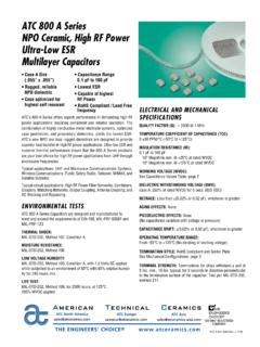
1 ELECTRICAL AND MECHANICALSPECIFICATIONSQUALITY FACTOR (Q):Greater than 10,000 ( pF to 100 pF) @ 1 than 2000 (110 pF to 1000 pF) @ 1 COEFFICIENT OF CAPACITANCE (TCC):0 30 PPM/ C (-55 C to +125 C)INSULATION RESISTANCE (IR) pF to 470 pF:106 Megohms min. @ +25 C at rated min. @ +125 C at rated pF to 1000 pF:105 Megohms min. @ +25 C at rated min. @ +125 C at rated VOLTAGE (WVDC): See Capacitance Values Table, p WITHSTANDING VOLTAGE (DWV):250% of rated WVDC for 5 :Less than ( or pF), whichever is EFFECTS:NonePIEZOELECTRIC EFFECTS:None(No capacitance variation with voltage or pressure).CAPACITANCE DRIFT: ( or pF), whichever is TEMPERATURE RANGE:From -55 C to +125 C (No derating of working voltage).TERMINATION STYLES:Available in various surface mountstyles. See Mechanical Configurations, page STRENGTH:Terminations for chips and pellets withstanda pull of 5 lbs. min., 10 lbs. typical, for 5 seconds in direction perpendi-cular to the termination surface of the 700 A Series NPOP orcelain and CeramicMultilayer capacitors Case A Size Capacitance Range (.)
2 055" x .055") pF to 1000 pF Low ESR/ESL Zero TCC Low Noise High Self-Resonance Rugged Construction Established Reliability (QPL) Extended WVDCup to 250 VDCATC, the industry leader, offers new improved ESR/ESL performancefor the 700 A Series RF/Microwave capacitors . The superior highself- resonance and zero TCC characteristic of this Series provide ex-cellent performance over a broad range of RF and microwave appli-cations requiring minimum drift. High density Porcelain and ceramicconstructions provide a rugged, hermetic functional applications: Bypass, Coupling, Tuning and circuit applications: Filters, Oscillators and TimingENVIRONMENTAL TESTSATC 700 A Series capacitors are designed and manufactured tomeet and exceed the requirements of EIA-198, MIL-PRF-55681and SHOCK:MIL-STD-202, Method 107, Condition RESISTANCE:MIL-STD-202, Method VOLTAGE HUMIDITY:MIL-STD-202, Method 103, Condition A, with Volts DC appliedwhile subjected to an environment of 85 C with 85% relative hu-midity for 240 hours TEST:MIL-STD-202, Method 108, for 2000 hours, at 125 WVDC # 001-813 Rev.
3 N, 9/14 ATC PART NUMBER CODE ATC700 A 6R 8 J W 150 X T Series Case Size Capacitance Code: First 2 significant digits for capacitance. R=Decimal Point Indicates number of zeros following digits of capacitance in picofarads except for decimal values. Capacitance Tolerance Laser Marking WVDC Termination Code The above part number refers to a 700 A Series (case size A) pF capacitor, J tolerance ( 5%)
4 , 150 WVDC, with W termination (Tin/Lead, Solder Plated over Nickel Barrier), laser marking and ATC Cap-Pac 700 A Capacitance ValuesVRMS = x WVDCSPECIAL VALUES, TOLERANCES, HIGHER WVDC AND MATCHING AVAILABLE. PLEASE CONSULT : EXTENDED WVDC DOES NOT APPLY TO CDR values in boldtype indicate Porcelain dielectric. All other capacitance values indicate Ceramic 700 A capacitors are available laser marked with ATC's identification, capacitance code and additional information and catalogs contact your ATC representative or call direct at (+1-631) factory for additional performance accepts orders for our parts using designations withor without the ATC prefix. Both methods of defining the part number are equivalent, , part numbers referenced with the ATC prefix are interchangeable toparts referenced without the ATC prefix. Customers are free to use eitherin specifying or procuring parts from American Technical TOLERANCECodeBCDFGJKMTol. pF pF pF 1% 2% 5% 10% 20%PackagingT - Tape and Reel, 1000 pc.
5 Qty.*TV - Vertical Orientation of Product,Tape and Reel, 1000 pc. qty.*I - Special Packaging. Consult Factory.*Consult ATC for other quantitiesATC Cap-Pac packaging (100 pc. qty. std.) is alsoavailable. For this option, leave last field (pF) WVDCSTD. (pF) WVDCSTD. (pF) WVDCSTD. (pF) WVDCSTD. , CB, C, , C,DB, C, J,K, MF, G, J,K, M150250200220240270300330360390430470510 5606206807508209101011111211312022242730 333639434751566268758291100110120130F, G, J,K, M150250200NA1511611812012212412713013313 6139143147151156162168175182191110215016 0180200220240270300330360390430470510560 6206807508209101000F, G,J, K, M15050N/AEXTENDED VOLTAGEEXTENDED VOLTAGEEXTENDED VOLTAGEEXTENDED VOLTAGEEXTENDED VOLTAGEEXT VOLAMERICAN TECHNICAL North a complete military catalog, request American Technical Ceramics document ATC 700 A capacitors : Mechanical ConfigurationsATCSERIES& SIZE& TYPEOUTLINESW/T IS ATERMINATION SURFACEBODY DIMENSIONSINCHES (mm)Lead and TerminationDimensions and MaterialsLENGTH(L)WIDTH(W)THICKNESS(T)OV ERLAP(Y)MATERIALS700 AWCDR12 BPA Solder +.
6 015 ( + ).055 .015( ).057 ( ) +.010 ( + )Tin/Lead, Solder PlatedoverNickel Barrier Termination700 APCDR12 BPA +.025 ( + ).055 .015( ).057 ( ) +.010 ( + )Heavy Tin / Lead Coated,over Nickel BarrierTermination700 ATN/AA SolderableNickel +.015 ( + ).055 .015( ).057 ( ) +.010 ( + )RoHS CompliantTin Plated overNickel Barrier Termination700 ACACDR11 BPA Gold +.015 ( + ).055 .015( ).057 ( ) +.010 ( + )RoHS CompliantGold Plated overNickel Barrier TerminationAMERICAN TECHNICAL North with values greater than 100 pF contain a trace magnetic element that may exhibit weak magnetic properties. ATC 700 A Non-Magnetic capacitors : Mechanical Configurations*4 Suggested Mounting Pad DimensionsATCSERIES& SIZE& TYPEOUTLINESW/T IS ATERMINATION SURFACEBODY DIMENSIONSINCHES (mm)LEAD AND TERMINATIONDIMENSIONS AND MATERIALSLENGTH(L)WIDTH(W)THICKNESS(T)OV ERLAP(Y)MATERIALS700 AWNM eetsRequire-mentsA Non-MagSolder +.025 ( + ).055 .015( ).057 ( ) +.010 ( + )Tin / Lead, Solder PlatedoverNon-Magnetic BarrierTermination700 APNM eetsRequire-mentsA +.
7 035 ( + ).055 .015( ).057 ( ) +.010 ( + )Heavy Tin / Lead Coated,overNon-Magnetic BarrierTermination700 ATNM eetsRequire-mentsA Non-MagSolderable +.025 ( + ).055 .015( ).057 ( ) +.010 ( + )RoHS CompliantTin Plated overNon-Magnetic BarrierTerminationAMERICAN TECHNICAL North are in 700 A Performance Data E 1000 MHz500 MHz150 MHz(Typical) 10100100010000110100C 150 MHz500 MHz1000 MHz(Typical) to 1000 pF) E 1000 MHz500 MHz150 MHz(Typical) 300 11010010001001000C 150 MHz500 MHz1000 MHz(Typical) 300 ESR VS. CAPACITANCEATC Series 700, CASE ACAPACITANCE (pF)( pF to 100 pF) ESR (Ohms)Q VS. CAPACITANCEATC Series 700, CASE ACAPACITANCE (pF)( pF to 100 pF) QESR VS. CAPACITANCEATC Series 700, CASE ACAPACITANCE (pF)(110 pF to 1000 pF) ESR (Ohms)Q VS. CAPACITANCEATC Series 700, CASE ACAPACITANCE (pF)(110 pF to 1000 pF)Q (Typical) TCC= 0 30 PPM/ C RESONANCE VS. CAPACITANCEATC Series 700, CASE AFREQUENCY (GHz)CAPACITANCE CHANGE VS.
8 TEMPERATUREATC Series 700, CASE ATEMPERATURE (Degrees C)% CHANGE IN CAPACITANCECAPACITANCE (pF)AMERICAN TECHNICAL North 700 A Performance Data 150 MHz500 MHz1000 MHzDotted line = Power dissipation limited Solid line = Voltage limited (Vrms) The current rating is based on a 65 C mountingsurface and a device thermal resistance of40 C/W. A power dissipation of W will resultin a case temperature of 125 C. 1101001000C 150 MHz500 MHz1000 MHzDotted line = Power dissipation limited The current rating is based on a 65 C mounting surface and a devicethermal resistance of 40 C/W. A power dissipation of W willresult in a case temperature of 125 of ATC products are subject to the terms and conditions contained in American Technical Ceramics Corp. Terms and Conditions of Sale (ATC document #001-992 Rev. B 12/05). Copies of these terms and conditions will be provided upon request.
9 They may also be viewed on ATC's website at Click on the link for Terms and Conditions of has made every effort to have this information as accurate as possible. However, no responsibility is assumed by ATC for its use, nor for any infringements ofrights of third parties which may result from its use. ATC reserves the right to revise the content or modify its product without prior notice. 1996 American Technical Ceramics Corp. All Rights # 001-813 Rev. N, 9/14 CURRENT RATING VS. CAPACITANCEATC Series 700, CASE ACAPACITANCE (pF)( pF to 100 pF) RMS CURRENT (Amps)CURRENT RATING VS. CAPACITANCEATC Series 700, CASE ACAPACITANCE (pF)(120 pF to 1000 pF)RMS CURRENT (Amps)1000 MHz150 MHz1000 MHz500 MHzDotted line = Power dissipation limitedSolid line = Voltage limited (Vrms)TypicalThe current rating is based on a 65 C mountingsurface and a device thermal resistance of40 C/W. A power dissipation of W will resultin a case temperature of 125 CURRENT RATING VS.
10 CAPACITANCEATC Series 700, CASE A, EXTENDED VOLTAGEC MHzDotted line = Power dissipation limited (Typical)150 MHz500 MHzThe current rating is based on a 65 C mountingsurface and a device thermal resistance of40 C/W. A power dissipation of W will resultin a case temperature of 125 RATING VS. CAPACITANCEATC Series 700, CASE A, EXTENDED VOLTAGECAPACITANCE (pF)(1 pF to 56 pF)RMS CURRENT (Amps)CURRENT RATING VS. CAPACITANCEATC Series 700, CASE A, EXTENDED VOLTAGECAPACITANCE (pF)(62 pF to 100 pF)RMS CURRENT (Amps)


