Transcription of ATC 800 A Series NPO Ceramic, High RF Power Multilayer ...
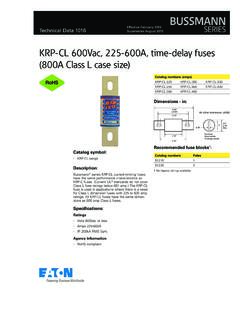
1 THE ENGINEERS CHOICE 800 a series npo ceramic , high RF Power Ultra-Low ESR Multilayer Capacitors Case A Size Capacitance Range (.055 x .055 ) pF to 100 pF Rugged, reliable Lowest ESR NPO dielectric Capable of highest Case optimized for RF Power highest self resonant RoHS Compliant/ Lead Free frequencyATC s 800 A Series offers superb performance in demanding high RF Power applications requiring consistent and reliable operation. The combination of highly conductive metal electrode systems, optimized case geometries, and proprietary dielectrics, yields the lowest ESR. ATC s new NPO low loss rugged dielectrics are designed to provide superior heat transfer in high RF Power applications. Ultra-low ESR and superior thermal performance insure that the 800 A Series products are your best choice for high RF Power applications from UHF through microwave applications: UHF and Microwave Communications Systems, Wireless Communications, Public Safety Radio, Telecom, WiMAX, and Satellite circuit applications: high RF Power Filter Networks, Combiners, Couplers, Matching Networks, Output Coupling, Antenna Coupling, and DC Blocking and TESTSATC 800 A Series Capacitors are designed and manufactured tomeet and exceed the requirements of EIA-198, MIL-PRF-55681 and SHOCK:MIL-STD-202, Method 107, Condition AMOISTURE RESISTANCE:MIL-STD-202, Method 106 LOW VOLTAGE HUMIDITY:MIL-STD-202, Method 103, Condition A, with Volts DC applied while subjected to an environment of 85 C with 85% relative humid-ity for 240 hours TEST.
2 MIL-STD-202, Method 108, for 2000 hours, at 125 C 200% WVDC appliedELECTRICAL AND MECHANICAL SPECIFICATIONSQUALITY FACTOR (Q): . 2000 @ 1 MHz TEMPERATURE COEFFICIENT OF CAPACITANCE (TCC):0 30 PPM/ C (-55 C to +125 C)INSULATION RESISTANCE (IR) pF to 100 pF: 105 Megohms min. @ +25 C at rated WVDC 104 Megohms min. @ +125 C at rated WVDCWORKING VOLTAGE (WVDC):See Capacitance Values Table, page 2 DIELECTRIC WITHSTANDING VOLTAGE (DWV):Case A: 250% of rated WVDC for 5 secs. (625 VDC)RETRACE: Less than ( or pF), whichever is greaterAGING EFFECTS: NonePIEZOELECTRIC EFFECTS: None(No capacitance variation with voltage or pressure)CAPACITANCE DRIFT: ( or pF), whichever is greaterOPERATING TEMPERATURE RANGE:From -55 C to +125 C (No derating of working voltage)TERMINATION STYLE: RoHS Compliant and Solder Plate See Mechanical Configurations, page 3 TERMINAL STRENGTH: Terminations for chips withstand a pull of 5 lbs.
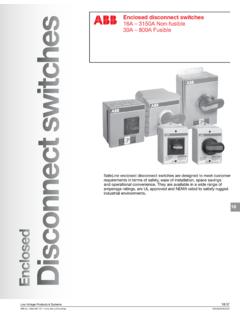
3 Min., 10 lbs. typical, for 5 seconds in direction perpendicular to the termination surface of the capacitor. Test per MIL-STD-202, method # 001-1032 Rev. J, 1/182 ATC PART NUMBER CODE ATC800 A 10 0 J T 250 X T Series Case Size Capacitance Code: First 2 significant digits for capacitance. R=Decimal Point Indicates number of zeros following digits of capacitance in picofarads except for decimal values. Capacitance Tolerance Laser Marking Termination Code WVDCP ackagingT - Tape & Reel: 500 and 4000 pc. qty. std.*TV - Vertical Orientation of Product, Tape & Reel: 500 and 4000 pc. qty. std.*I - Special Packaging. Consult Factory. *Consult ATC for other quantitiesATC 800 A Capacitance ValuesVRMS = X WVDCSPECIAL VALUES, TOLERANCES AND MATCHING AVAILABLE. PLEASE CONSULT TOLERANCECodeBCDFGJKMTol. pF pF pF 1% 2% 5% 10% 20% CAP. CAP. CAP.
4 CAP. CAP. CAP. CODE (pF) TOL. RATED WVDC CODE (pF) TOL. RATED WVDC CODE (pF) TOL. RATED WVDC 0R1 2R2 160 16 0R2 2R4 180 18 0R3 2R7 200 20 0R4 3R0 220 22 0R5 3R3 240 24 0R6 3R6 270 27 0R7 3R9 300 30 0R8 4R3 330 33 0R9 4R7 360 36 1R0 5R1 390 39 1R1 250 5R6 250 430 43 250 1R2 6R2 470 47 1R3 6R8 510 51 1R4 7R5 560 56 1R5 8R2 620 62 1R6 9R1 680 68 1R7 100 10 750 75 1R8 110 11 820 82 1R9 120 12 910 91 2R0 130 13
5 101 100 2R1 150 15 BB, CB, C,DB, C,DB, C, J, K, MF, G, J, K, MF, G, J, K, MThe above part number refers to a 800 A Series (case size A) 10 pF capacitor, J tolerance ( 5%), 150 WVDC, with T termination (Tin Plated over Nickel Barrier, RoHS Compliant), laser marking and tape and reel additional information and catalogs contact your ATC representative or call direct at (+1-631) factory for additional performance accepts orders for our parts using designations with or without the ATC prefix. Both methods of defining the part number are equivalent, , part numbers referenced with the ATC prefix are interchangeable to parts referenced without the ATC prefix. Customers arefree to use either in specifying or procuring parts from American Technical TECHNICAL North Electrode Orientation Horizontal Electrode Orientation B A C D B T W T L W 100 100 L 100A Normal high Density.
6 070 .050 .050 .030 .030 .030 .090 .130 A Min. B Min. C Min. D Min. Pad Size Normal high Density .080 .060 .050 .030 .030 .030 .090 .130 Vertical Mount Horizontal Mount Case A Suggested Mounting Pad DimensionsATC 800 A Capacitors: Mechanical ConfigurationsATC TERM. CODECASE SIZE & TYPEOUTLINESW/T IS A TERMINATION SURFACEBODY DIMENSIONS Inches (mm)LENGTH (L)WIDTH (W)THICKNESS (T)OVERLAP (Y)MATERIALLEAD AND TERMINATION DIMENSIONS AND MATERIALSTA Solder +.015 ( + ).055 .015 ( ).057 ( ) +.010 ( + )RoHS CompliantTin Plated over Nickel Barrier TerminationTin / Lead Solder Plated over Nickel Barrier TerminationLTWYATC Series & CASE SIZE800 AWA Solderable Nickel +.015 ( + ).055 .015 ( ).057 ( ) +.010 ( + )LTWY800 AATC 800 A Non-Magnetic Capacitors: Mechanical ConfigurationsATC TERM. CODECASE SIZE & TYPEOUTLINESW/T IS A TERMINATION SURFACEBODY DIMENSIONS Inches (mm)LENGTH (L)WIDTH (W)THICKNESS (T)OVERLAP (Y)MATERIALLEAD AND TERMINATION DIMENSIONS AND +.
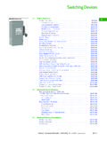
7 015 ( + ).055 .015 ( ).057 ( ) +.010 ( + )RoHS CompliantTin Plated over Non-Magnetic Barrier TerminationLTWYATC Series & CASE SIZE800AA Non-Mag Solderable BarrierAMERICAN TECHNICAL North are in 800 A Performance DataATC 800 A Series Data Sheet Test Condition DescriptionCapacitors horizontally mounted in Series microstrip configuration on thick Rogers RO4350 softboard, 52-mils wide 1/2 oz. Cu = lowest frequency at which S11 response, referenced at capacitor edge, crosses real axis on Smith = lowest frequency at which there is a notch in S21 magnitude A FSR & FPR vs. Capacitance110100110100 Capacitance (pF)Frequency (GHz)Frequency (GHz)(Typical)Vert FprVert FsrHoriz FprHoriz - pF800A - pF800A - 10 pF 800A - 33 pF800A - 100 pF800 A ESR vs. FrequencyFrequency (MHz)ESR (Ohms)4 AMERICAN TECHNICAL North of ATC products are subject to the terms and conditions contained in American Technical Ceramics Corp.
8 Terms and Conditions of Sale (ATC document #001-992). Copies of these terms and conditions will be provided upon request. They may also be viewed on ATC s website at Click on the link for Terms and Conditions of has made every effort to have this information as accurate as possible. However, no responsibility is assumed by ATC for its use, nor for any infringements of rights of third parties which may result from its use. ATC reserves the right to revise the content or modify its product without prior notice. 2006 American Technical Ceramics Corp. All Rights Reserved. ATC # 001-1032 Rev. J, 1/185 Temperature (Degrees C)% Change in Capacitance800A Capacitance Change vs. Temperature TCC= 0 30 800 A Performance DataAMERICAN TECHNICAL North