Transcription of ATC Resistors and Terminations: Engineering Guidelines
1 ATC high POWER RESISTIVE PRODUCTS. ATC Resistors and Terminations: Engineering Guidelines Design, Test and Measurement, Performance and Mounting A M E R I C A N T E C H N I C A L C E R A M I C S. ATC North America ATC Europe ATC Asia c er am ic s .c om MEASUREMENT AND PERFORMANCE OF CHIP Resistors AND TERMINATIONS. As the wireless revolution extends component requirements up- Typical thick-film thicknesses are on the order of mils. ward in frequency, higher in operating power, and smaller in size, Silver, platinum-silver, or palladium-silver are industry standard performance demands on resistive devices grow ever more strin- conductors; ruthenium dioxide is a typical core material for the gent. Chip terminations made with resistive films are typically resistive paste.
2 Different resistivity values are achieved by chang- used as dummy loads or to absorb power that appears at the nor- ing the resistive paste composition the proportion of resistive mally isolated ports of circulators, couplers, and hybrids as a result particles, glass frit, and organic binder and by altering or aug- of mismatches, imperfect directivity, or imbalances somewhere menting the curing cycle. Final resistance values are achieved by in the system, while chip Resistors perform the same function in active trimming, usually with a laser. Wilkinson power dividers. Reliable design places conservative lim- its on the maximum temperature of the resistive film and uses substrate materials that closely match the film's coefficient of A. Conductive thermal expansion (TCE).
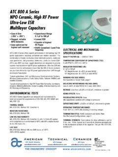
3 Contact Limiting the resistive film's temperature requires an insulating sub- strate with high thermal conductivity. Other desirable properties include temperature-independent (over a reasonable range) di- Section A-A. Resistive electric constant at microwave frequencies, physical strength, film good adhesion to film resistive materials, and imperviousness to humidity and processing chemicals used in microelectronic as- A. Groundplane sembly. For many years in the USA beryllium oxide (BeO) has been the substrate of choice to meet these requirements despite the Figure 1: A Chip resistor fact that BeO dust and powder are known to be hazardous and Thin-film coatings are typically applied by sputtering or evapora- to require special handling and disposal techniques. The interna- In the latter process, a source material is heated in an evac- tional community, however, has opposed the use of BeO, and so uated chamber until its vapor pressure is close to 10 2 torr and in recent years an alternate material, aluminum nitride (AlN), has found increasing use as a substitute.
4 Table 1 compares typical source atoms evaporate onto a nearby target substrate. In the properties of AlN to BeO; data for 99% Alumina is included for former process, the substrate to be coated and a target made of reference. the material to be sputtered are placed in a chamber filled with inert gas at low pressure. An arc is struck in the gas, with the Our focus herein will be on the Aluminum Nitride resistive prod- substrate placed at ground electrical potential and the target at uct line developed at ATC and will discuss design considerations a high negative potential. The target's high potential causes it to and test methodologies for bare chips as well as those mounted be bombarded by positive gas ions in the plasma, to the point in various configurations. where atoms (or molecular fragments) are dislodged that migrate and adhere to the substrate.
5 Typical thicknesses of sputtered ma- TABLE 1: terials are in the hundreds or low thousands of angstroms;. Physical Properties of Aluminum Nitride and Beryllium Oxide greater thicknesses are achieved by plating up, a separate Al203, process. ATC's current implementation for most resistive products Property AIN BeO 99%. is in sputtered thin film. Conductors are silver-plated copper; the Dielectric constant @ 1 MHz resistive material is tantalum nitride. Different resistivity values are Loss tangent @ 1 MHz achieved by controlling the Ta2N thickness and the way in which Thermal conductivity (W/mK) @ 25 C 180 275 25. it is annealed. An important feature of tantalum nitride is its (so- @ 100 C 150 200 . called) anodic property: By either electrical or thermal means a @ 200 C 125 150.
6 Surface oxide layer can be created that acts to seal and protect Thermal expansion coefficient (10 6/ C) the underlying film. As with thick film, final resistance values are Density (g/cm3) usually achieved by laser trimming. STRUCTURES, IMPLEMENTATIONS, AND CONFIGURATIONS Figure 2 depicts a chip termination . Terminations usually have Figure 1 depicts a basic chip resistor consisting of a resistive film two features not found on simple Resistors : an edge wraparound between two conductive terminations. A conductive ground that connects one end of the resistor to the ground plane and a plane covers the chip's bottom side. The chip body, or substrate, structure or pattern that matches the impedance of the resistive is comprised of AlN. film to some specified value, most commonly 50 ohms.
7 Impedance- In general, the chip's resistive section and conductors can be im- matching plemented in either thick-film, thin-film, or some combination of structure A. technologies. As used here, the terms thick and thin refer to the Conductive contact fabrication process, as well as the resultant film depth dimension. In thick-film technology, a conductive or resistive paste is applied to the substrate using a screen printer. The paste is then cured Section A-A. Groundplane according to a prescribed time-temperature cycle. Resistive film A. Wraparound Figure 2: A Chip termination A M E R I C A N T E C H N I C A L C E R A M I C S. ATC North America ATC Europe ATC Asia 2. c er am ic s .c om MEASUREMENT AND PERFORMANCE OF CHIP Resistors AND TERMINATIONS. Both Resistors and terminations are available in several different over hundreds or thousands of hours of operation.
8 It depends package styles. Those shown in Figs. 1 and 2 are meant to be on the temperature reached by the film (which, among many fac- mounted (usually by soldering) to a metallic ground plane, either tors, in turn depends on the properties of the mounting surface). in a cutout in a microstrip board or adjacent to a board edge (see and may depend on applied voltage as well. Property (2) may af- Figure 3a). The contact area on the chip has a silver tab parallel- fect the lifetime or behavior of other devices in proximity to the gap welded to it; the free end of the tab is soldered to the mi- resistive chip. Properties (3) and (4) are generally short-term . crostrip trace. Heat generated in the resistive film is conducted change occurs over a few minutes measures of stability, by the chip substrate to the ground plane.
9 Other configurations usually presented as TCR, the Temperature Coefficient of Resist- are designed to avoid the necessity of a cutout or proximity to a ance and VCR, the Voltage Coefficient of Resistance. Property (5). board edge; these are so-called surface mount parts and are typ- is a fundamental measure of electrical performance needed for ically soldered to a via-patch on the PC board's top surface. The operation of the circuit or sub-system in which the resistive chip via patch transfers the generated heat to the ground plane (see is used. Figure 3b). A schematic overview of the various chip configura- Resistive chip design must simultaneously consider properties (1). tions and their designations is shown in Figure 4. Note that the through (5), because of the tradeoffs involved.
10 In practice, two CW style has no ground conductor; heat from the resistive film problems arise, usually with (1), (2), and (5): End-users fail to pre- can be removed only through the end contacts, by convection, cisely define the measurement conditions and vendors do likewise or by radiation. In practice, all resistive films are covered with a with their specifications. thin layer of a special epoxy that helps protect against solvents, moisture, handling, and other environmental hazards. Other Vendor power ratings, for example, are usually given for parts packaging options (not shown) include ceramic covers for addi- mounted on "an ideal heat sink," or "an infinite heat sink". tional environmental protection and marking, and flange mounts without explanation as to how a user can de-rate the part for that enable parts to be screwed down to mounting surfaces operation on a real heat sink or, for that matter, how the ven- rather than soldered.