Transcription of Atmel ATmega640/V-1280/V-1281/V-2560/V-2561/V
1 2549Q AVR 02/2014 Features High Performance, Low Power Atmel AVR 8-Bit Microcontroller Advanced RISC Architecture 135 Powerful Instructions Most Single Clock Cycle Execution 32 8 General Purpose Working Registers Fully Static Operation Up to 16 MIPS Throughput at 16 MHz On-Chip 2-cycle Multiplier High Endurance Non-volatile Memory Segments 64K/128K/256 KBytes of In-System Self-Programmable Flash 4 Kbytes EEPROM 8 Kbytes Internal SRAM Write/Erase Cycles:10,000 Flash/100,000 EEPROM Data retention: 20 years at 85 C/ 100 years at 25 C Optional Boot Code Section with Independent Lock Bits In-System Programming by On-chip Boot Program True Read-While-Write Operation Programming Lock for Software Security Endurance: Up to 64 Kbytes Optional External Memory Space Atmel QTouch library support capacitive touch buttons, sliders and wheels QTouch and QMatrix acquisition Up to 64 sense channels JTAG (IEEE std.)
2 Compliant) Interface Boundary-scan Capabilities According to the JTAG Standard Extensive On-chip Debug Support Programming of Flash, EEPROM, Fuses, and Lock Bits through the JTAG Interface Peripheral Features Two 8-bit Timer/Counters with Separate Prescaler and Compare Mode Four 16-bit Timer/Counter with Separate Prescaler, Compare- and Capture Mode Real Time Counter with Separate Oscillator Four 8-bit PWM Channels Six/Twelve PWM Channels with Programmable Resolution from 2 to 16 Bits(ATmega1281/2561, ATmega640/1280/2560) Output Compare Modulator 8/16-channel, 10-bit ADC (ATmega1281/2561, ATmega640/1280/2560) Two/Four Programmable Serial USART (ATmega1281/2561, ATmega640/1280/2560) Master/Slave SPI Serial Interface Byte Oriented 2-wire Serial Interface Programmable Watchdog Timer with Separate On-chip Oscillator On-chip Analog Comparator Interrupt and Wake-up on Pin Change Special Microcontroller Features Power-on Reset and Programmable Brown-out Detection Internal Calibrated Oscillator External and Internal Interrupt Sources Six Sleep Modes: Idle, ADC Noise Reduction, Power-save, Power-down, Standby,and Extended Standby I/O and Packages 54/86 Programmable I/O Lines (ATmega1281/2561, ATmega640/1280/2560) 64-pad QFN/MLF, 64-lead TQFP (ATmega1281/2561) 100-lead TQFP, 100-ball CBGA (ATmega640/1280/2560) RoHS/Fully Green Temperature Range: -40 C to 85 C Industrial Ultra-Low Power Consumption Active Mode: 1 MHz.
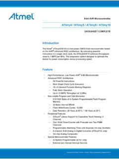
3 500 A Power-down Mode: A at Speed Grade: ATmega640V/ATmega1280V/ATmega1281V: 0 - 4 MHz @ - , 0 - 8 MHz @ - ATmega2560V/ATmega2561V: 0 - 2 MHz @ - , 0 - 8 MHz @ - ATmega640/ATmega1280/ATmega1281: 0 - 8 MHz @ - , 0 - 16 MHz @ - ATmega2560/ATmega2561: 0 - 16 MHz @ - ATmega640/V-1280/V-1281/V-2560/V-2561/V8 -bit Atmel Microcontroller with 16/32/64KB In-System Programmable FlashDATASHEET2 ATmega640/V-1280/V-1281/V-2560/V-2561/V [DATASHEET]2549Q AVR 02/20141. Pin ConfigurationsFigure ATmega640/1280/2560 GNDVCCPA0 (AD0)PA1 (AD1)PA2 (AD2)PA3 (AD3)PA4 (AD4)PA5 (AD5)PA6 (AD6)PA7 (AD7)PG2 (ALE)AVCCGNDAREFPF0 (ADC0)PF1 (ADC1)PF2 (ADC2)PF3 (ADC3)PF4 (ADC4/TCK)PF5 (ADC5/TMS)PF6 (ADC6/TDO)PF7 (ADC7/TDI)100999897969594939291908988878 6858483828180797877761234567891011121314 1516171819202122232425757473727170696867 6665646362616059585756555453525126282931 2736303235373334383940414243444546474849 50PK0 (ADC8/PCINT16)PK1 (ADC9/PCINT17)PK2 (ADC10/PCINT18)PK3 (ADC11/PCINT19)PK4 (ADC12/PCINT20)PK5 (ADC13/PCINT21)PK6 (ADC14/PCINT22)PK7 (ADC15/PCINT23)(OC2B) PH6(TOSC2) PG3(TOSC1) PG4 RESET(T4) PH7(ICP4) PL0 VCCGNDXTAL2 XTAL1PL6PL7 GNDVCC(OC0B) PG5 VCCGND(RXD2) PH0(TXD2) PH1(XCK2) PH2(OC4A) PH3(OC4B) PH4(OC4C) PH5(RXD0/PCINT8) PE0(TXD0) PE1(XCK0/AIN0)
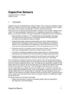
4 PE2(OC3A/AIN1) PE3(OC3B/INT4) PE4(OC3C/INT5) PE5(T3/INT6) PE6(CLKO/ICP3/INT7) PE7(SS/PCINT0) PB0(SCK/PCINT1) PB1(MOSI/PCINT2) PB2(MISO/PCINT3) PB3(OC2A/PCINT4) PB4(OC1A/PCINT5) PB5(OC1B/PCINT6) PB6(OC0A/OC1C/PCINT7) PB7PC7 (A15)PC6 (A14)PC5 (A13)PC4 (A12)PC3 (A11)PC2 (A10)PC1 (A9)PC0 (A8)PG1 (RD)PG0 (WR)(TXD1/INT3) PD3(ICP1) PD4(XCK1) PD5(T1) PD6(T0) PD7(SCL/INT0) PD0(SDA/INT1) PD1(RXD1/INT2) PD2(ICP5) PL1(T5) PL2(OC5A) PL3(OC5B) PL4PJ6 (PCINT15)PJ5 (PCINT14)PJ4 (PCINT13)PJ3 (PCINT12)PJ2 (XCK3/PCINT11)PJ1 (TXD3/PCINT10)PJ0 (RXD3/PCINT9)PJ7(OC5C) PL5 INDEX CORNER3 ATmega640/V-1280/V-1281/V-2560/V-2561/V [DATASHEET]2549Q AVR 02/2014 Figure ATmega640/1280/2560 Note:The functions for each pin is the same as for the 100 pin packages shown in Figure 1-1 on page viewBottom viewTable ATmega640/1280/256012345678910 AGNDAREFPF0PF2PF5PK0PK3PK6 GNDVCCBAVCCPG5PF1PF3PF6PK1PK4PK7PA0PA2 CPE2PE0PE1PF4PF7PK2PK5PJ7PA1PA3 DPE3PE4PE5PE6PH2PA4PA5PA6PA7PG2 EPE7PH0PH1PH3PH5PJ6PJ5PJ4PJ3PJ2 FVCCPH4PH6PB0PL4PD1PJ1PJ0PC7 GNDGGNDPB1PB2PB5PL2PD0PD5PC5PC6 VCCHPB3PB4 RESETPL1PL3PL7PD4PC4PC3PC2 JPH7PG3PB6PL0 XTAL2PL6PD3PC1PC0PG1 KPB7PG4 VCCGNDXTAL1PL5PD2PD6PD7PG04 ATmega640/V-1280/V-1281/V-2560/V-2561/V [DATASHEET]2549Q AVR 02/2014 Figure ATmega1281/2561 Note:The large center pad underneath the QFN/MLF package is made of metal and internally connected to GND.
5 It should be soldered or glued to the board to ensure good mechanical stability. If the center pad is left unconnected, the pack-age might loosen from the board.(RXD0/PCINT8/PDI) PE0(TXD0/PDO) PE1(XCK0/AIN0) PE2(OC3A/AIN1) PE3(OC3B/INT4) PE4(OC3C/INT5) PE5(T3/INT6) PE6(ICP3/ CLKO/INT7) PE7(SS/PCINT0) PB0(OC0B) PG5(SCK/ PCINT1) PB1(MOSI/ PCINT2) PB2(MISO/ PCINT3) PB3(OC2A/ PCINT4) PB4(OC1A/PCINT5) PB5(OC1B/PCINT6) PB6(OC0A/OC1C/PCINT7) PB7(TOSC2) PG3(TOSC1) PG4 RESETVCCGNDXTAL2 XTAL1(SCL/INT0) PD0(SDA/INT1) PD1(RXD1/INT2) PD2(TXD1/INT3) PD3(ICP1) PD4(XCK1) PD5PA3 (AD3)PA4 (AD4)PA5 (AD5)PA6 (AD6)PA7 (AD7)PG2 (ALE)PC7 (A15)PC6 (A14)PC5 (A13)PC4 (A12)PC3 (A11)PC2 (A10)PC1 (A9)PC0 (A8)PG1 (RD)PG0 (WR)AVCCGNDAREFPF0 (ADC0)PF1 (ADC1)PF2 (ADC2)PF3 (ADC3)PF4 (ADC4/TCK)PF5 (ADC5/TMS)PF6 (ADC6/TDO)PF7 (ADC7/TDI)GNDVCCPA0 (AD0)PA1 (AD1)PA2 (AD2)(T1) PD6(T0)
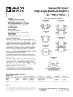
6 PD7 INDEX CORNER1234567891011121314151664636261605 9585756555453525150494847464544434241403 9383736353433171819202122232425262728293 031325 ATmega640/V-1280/V-1281/V-2560/V-2561/V [DATASHEET]2549Q AVR 02/20142. OverviewThe ATmega640/1280/1281/2560/2561 is a low-power CMOS 8-bit microcontroller based on the AVR enhancedRISC architecture. By executing powerful instructions in a single clock cycle, theATmega640/1280/1281/2560/2561 achieves throughputs approaching 1 MIPS per MHz allowing the systemdesigner to optimize power consumption versus processing DiagramFigure DiagramThe Atmel AVR core combines a rich instruction set with 32 general purpose working registers. All the 32 regis-ters are directly connected to the Arithmetic Logic Unit (ALU), allowing two independent registers to be accessed inone single instruction executed in one clock cycle.
7 The resulting architecture is more code efficient while achievingthroughputs up to ten times faster than conventional CISC microcontrollers. CPUGNDVCCRESETPo w e rSupervisionPOR / BOD &RESETWat chd ogOscillatorWat chd ogTi m erOscillatorCi r c u i t s /Cl o c kGen er at i o C ( 8 ) A ( 8 )PORT D ( 8 ) B ( 8 ) RT E ( 8 ) F ( 8 ) J ( 8 ) G ( 6 )PORT H ( 8 ) K ( 8 ) L ( 8 ) MJTAG8 bit T/ C 08 bit T/ C 216 bit T/ C 116 bit T/ C 3 SRA MFLASH16 bit T/ C 416 bit T/ C 5 USART 2 USART 1 USART 0 Internal Bandgap referenceAnalog Co m p ar at o rA/ DCo n v e r t e rUSART 3 NOTE:Shaded p ar t s onl y avai l ab l ein t he 100-pin version. Complete functionality fort h e A D C, T/ C4 , an d T/ C5 o n l y available in t he 100-pin [DATASHEET]2549Q AVR 02/2014 The ATmega640/1280/1281/2560/2561 provides the following features: 64K/128K/256K bytes of In-System Pro-grammable Flash with Read-While-Write capabilities, 4 Kbytes EEPROM, 8 Kbytes SRAM, 54/86 general purposeI/O lines, 32 general purpose working registers, Real Time Counter (RTC), six flexible Timer/Counters with com-pare modes and PWM, four USARTs, a byte oriented 2-wire Serial Interface, a 16-channel, 10-bit ADC withoptional differential input stage with programmable gain, programmable Watchdog Timer with Internal Oscillator,an SPI serial port, IEEE std.
8 Compliant JTAG test interface, also used for accessing the On-chip Debugsystem and programming and six software selectable power saving modes. The Idle mode stops the CPU whileallowing the SRAM, Timer/Counters, SPI port, and interrupt system to continue functioning. The Power-downmode saves the register contents but freezes the Oscillator, disabling all other chip functions until the next interruptor Hardware Reset. In Power-save mode, the asynchronous timer continues to run, allowing the user to maintain atimer base while the rest of the device is sleeping. The ADC Noise Reduction mode stops the CPU and all I/O mod-ules except Asynchronous Timer and ADC, to minimize switching noise during ADC conversions. In Standbymode, the Crystal/Resonator Oscillator is running while the rest of the device is sleeping.
9 This allows very faststart-up combined with low power consumption. In Extended Standby mode, both the main Oscillator and theAsynchronous Timer continue to offers the QTouch library for embedding capacitive touch buttons, sliders and wheels functionality into AVRmicrocontrollers. The patented charge-transfer signal acquisition offersrobust sensing and includes fullydebounced reporting of touch keys and includes Adjacent Key Suppression (AKS ) technology for unambiguousdetection of key events. The easy-to-use QTouch Suite toolchain allows you to explore, develop and debug yourown touch device is manufactured using the Atmel high-density nonvolatile memory technology. The On-chip ISP Flashallows the program memory to be reprogrammed in-system through an SPI serial interface, by a conventional non-volatile memory programmer, or by an On-chip Boot program running on the AVR core.
10 The boot program can useany interface to download the application program in the application Flash memory. Software in the Boot Flashsection will continue to run while the Application Flash section is updated, providing true Read-While-Write opera-tion. By combining an 8-bit RISC CPU with In-System Self-Programmable Flash on a monolithic chip, the AtmelATmega640/1280/1281/2560/2561 is a powerful microcontroller that provides a highly flexible and cost effectivesolution to many embedded control ATmega640/1280/1281/2560/2561 AVR is supported with a full suite of program and system developmenttools including: C compilers, macro assemblers, program debugger/simulators, in-circuit emulators, and [DATASHEET]2549Q AVR 02 Between ATmega1281/2561 and ATmega640/1280/2560 Each device in the ATmega640/1280/1281/2560/2561 family differs only in memory size and number of pins.