Transcription of ATP 6-02.53 TECHNIQUES FOR TACTICAL RADIO …
1 ATP TECHNIQUES FOR TACTICAL RADIO OPERATIONS FEBRUARY 2020 DISTRIBUTION RESTRICTION: Approved for public release; distribution is unlimited. This publication supersedes ATP , dated 7 January 2016. Headquarters, Department of the Army This publication is available at the Army Publishing Directorate Website ( ) and the Central Army Registry site ( ). *ATP RESTRICTION: Approved for public release; distribution is unlimited. *This publication supersedes ATP , dated 7 January i Army TECHNIQUES Publication No. Headquarters Department of the Army Washington, DC, 13 February 2020 TECHNIQUES for TACTICAL RADIO Operations Contents Page vii INTRODUCTION .. ix Chapter 1 OVERVIEW .. 1-1 TACTICAL Radios .. 1-1 TACTICAL RADIO Networks .. 1-2 Network Management Planning Tools .. 1-4 Capabilities .. 1-6 Land Mobile RADIO .. 1-6 Combat Survivor Evader Locator .. 1-7 Chapter 2 TACTICAL RADIO EMPLOYMENT BY ECHELON .. 2-1 Combatant Commander Communications Team.
2 2-1 Signal Command (Theater) .. 2-3 Corps and Below .. 2-4 Special Operations Forces .. 2-5 TACTICAL Command Post .. 2-6 Chapter 3 TACTICAL RADIO PLATFORMS .. 3-1 Section I Legacy and Enduring RADIO Platforms .. 3-1 Single-Channel Ground and Airborne RADIO System .. 3-1 Defense Advanced Global Positioning System Receiver .. 3- 12 MicroLight Personal Software-Defined Networked RADIO .. 3- 13 high frequency Radios .. 3- 13 Blue Force Tracking .. 3- 18 Force XXI Battle Command, Brigade and Below Joint Battle Command Platform . 3- 19 Force XXI Battle Command, Brigade and Below Joint Capabilities Release .. 3- 19 Section II Software Defined RADIO Platforms .. 3- 19 Handheld Manpack Small Form Fit .. 3- 20 Manpack RADIO .. 3- 21 Chapter 4 WAVEFORMS AND WAVEFORM APPLICATIONS .. 4-1 Lower Tier Waveforms .. 4-1 Waveform Applications .. 4-2 Chapter 5 VHF RADIOS .. 5-1 Multiband Inter/Intra Team RADIO .. 5-1 Wideband Networking Handheld RADIO .
3 5-2 Multichannel Manpack RADIO .. 5-3 Preface ii ATP 13 February 2020 Chapter 6 ULTRAHIGH frequency RADIOS .. 6-1 Multifunctional Information Distribution System .. 6-1 TACTICAL Digital Information Link Joint Terminals .. 6-1 Joint TACTICAL Information Distribution System .. 6-2 Battlefield Awareness and Targeting System-Dismounted .. 6-3 Chapter 7 AIRBORNE RADIOS .. 7-1 AN/ARC-201 RADIO .. 7-1 AN/ARC-210 RADIO .. 7-1 AN/ARC-220 RADIO .. 7-2 AN/ARC-231 RADIO .. 7-2 AN/ARC-186 RADIO .. 7-3 Chapter 8 ANTENNA TECHNIQUES .. 8-1 Antenna TECHNIQUES Overview .. 8-1 high frequency Antenna Location Considerations .. 8-1 Ground Effects .. 8-9 Grounded Antenna Theory .. 8- 10 Antenna Length .. 8- 12 Antenna Orientation .. 8- 13 Improvement of Marginal Communications .. 8- 15 Types of Antennas .. 8- 15 Field Repair .. 8- 30 Chapter 9 TACTICAL RADIO KEY MANAGEMENT .. 9-1 Key Management Infrastructure .. 9-1 Key Distribution .. 9-2 Automated Communications Engineering Software.
4 9-2 Loadsets .. 9-4 Chapter 10 ELECTRONIC WARFARE AND PROTECTION TECHNIQUES .. 10-1 Electronic Warfare .. 10-1 Electronic Protection Responsibilities .. 10-3 Communications Planning Process .. 10-5 Signal Security .. 10-7 Emission Control .. 10-7 Preventive Electronic Protection TECHNIQUES .. 10-8 Single-Channel Ground and Airborne RADIO System Anti-Jamming .. 10-14 Electronic Warfare for Single-Channel TACTICAL Satellite .. 10-15 Counter RADIO -Controlled Improvised Explosive Device Electronic Warfare .. 10-17 Purposeful Interference .. 10-17 Electromagnetic Interference .. 10-17 Appendix A frequency MODULATION RADIO NETWORKS .. A-1 Appendix B SINGLE-CHANNEL RADIO COMMUNICATIONS TECHNIQUES .. B-1 Appendix C ANTENNA SELECTION .. C-1 Appendix D COMMUNICATIONS IN AUSTERE ENVIRONMENTS .. D-1 Appendix E JULIAN DATE, SYNCHRONIZATION TIME, AND TIME CONVERSION .. E-1 Appendix F RADIO COMPROMISE RECOVERY PROCEDURES .. F-1 Appendix G DATA COMMUNICATIONS.
5 G-1 Appendix H COSITE INTERFERENCE .. H-1 Appendix I RADIO OPERATING PROCEDURES .. I-1 Appendix J FIELD REPAIR OF ANTENNAS .. J -1 Preface 13 February 2020 ATP iii Appendix K SINGLE-CHANNEL TACTICAL SATELLITE COMMUNICATIONS .. K-1 GLOSSARY .. Glossary-1 REFERENCES .. References-1 INDEX .. Index-1 Figures Figure 3-1. Retransmission operations .. 3- 10 Figure 3-2. Defense Advanced Global Positioning System receiver .. 3- 13 Figure 8-1. Transmitter and receiver connection example .. 8-2 Figure 8-2. Components of electromagnetic waves .. 8-3 Figure 8-3. Solid radiation patterns .. 8-4 Figure 8-4. Vertically polarized wave .. 8-5 Figure 8-5. Horizontally polarized wave .. 8-6 Figure 8-6. Circular polarization .. 8-7 Figure 8-7. Antenna take-off angle .. 8-9 Figure 8-8. Quarter-wave antenna connected to ground .. 8- 10 Figure 8-9. Wire counterpoise .. 8- 12 Figure 8-10. Beamwidth .. 8- 14 Figure 8-11. Example of a declination diagram.
6 8 - 14 Figure 8-12. Near-vertical incidence skywave antenna, AS-2259/GR .. 8- 16 Figure 8-13. V antenna .. 8- 17 Figure 8-14. Vertical half-rhombic antenna .. 8 - 18 Figure 8-15. Long-wire antenna .. 8- 19 Figure 8-16. Sloping-V antenna .. 8- 20 Figure 8-17. Inverted L antenna .. 8- 21 Figure 8-18. Near-vertical incidence skywave propagation .. 8- 22 Figure 8-19. Whip antenna .. 8- 23 Figure 8-20. Whip antennas mounted on a 8- 24 Figure 8-21. OE-303 half-rhombic VHF antenna .. 8- 26 Figure 8-22. Half-wave dipole (doublet) antenna .. 8- 27 Figure 8-23. Center-fed half-wave antenna .. 8 - 28 Figure 8-24. Improvised vertical half-wave antenna .. 8- 29 Figure 8-25. Field repair of broken whip antennas .. 8- 31 Figure 8-26. Examples of field expedient antenna insulators .. 8- 32 Figure 8-27. Repaired antenna guy lines and masts .. 8- 33 Figure 10-1. Local interference resolution (Army victim) .. 10-19 Figure 10-2.
7 Interference resolution (Army source) .. 10-20 Figure A-1. Structure of a division command network ..A-3 Figure A-2. Example of a brigade administrative and logistics Figure A-3. Example of a division operations and intelligence communications Preface iv ATP 13 February 2020 Figure A-4. Example of a corps medical operations network .. A-6 Figure A-5. Example of a medical operations network in a division .. A-7 Figure A-6. Example of a division sustainment area command network .. A-8 Figure A-7. Example of a division HF command network .. A-9 Figure A-8. Example of a cavalry squadron HF data network .. A- 10 Figure B-1. Radiation of RADIO waves from a vertical antenna .. B-3 Figure B-2. Wavelength of a RADIO wave .. B-3 Figure B-3. Principal paths of RADIO waves .. B-4 Figure B-4. Possible routes for ground waves .. B-4 Figure B-5. Average layer distribution of the ionosphere .. B-6 Figure B-6. Skywave transmission paths.
8 B-8 Figure B-7. Skywave transmission hop B-9 Figure B-8. Wave shapes .. B- 13 Figure B-9. Amplitude modulation system .. B- 14 Figure B-10. Single-sideband system .. B- 15 Figure C-1. 32-foot vertical whip, vertical antenna pattern .. C-3 Figure E-1. World time zone map .. E-5 Figure H-1. Possible antenna stacks .. H-3 Figure J-1. Field repair of broken whip antennas .. J-1 Figure J-2. Examples of field expedient antenna insulators .. J-2 Figure J-3. Repaired antenna guy lines and masts .. J-3 Figure K-1. Single-Channel Anti-Jam Man-Portable terminal interface with combat net RADIO .. K-4 Tables Table 3-1. Comparison of SINCGARS versions and components .. 3-3 Table 3-2. SINCGARS enhancements comparison .. 3-5 Table 3-2. SINCGARS enhancements comparison (continued) .. 3-6 Table 3-3. Minimum antenna separation distance .. 3- 11 Table 3-4. AN/VRC-100 configurations .. 3- 15 Table 3-5. Automatic link establishment system handshake.
9 3- 17 Table 3-6. Notional link quality analysis matrix for a RADIO (B3B) .. 3- 17 Table 8-1. Antenna length calculations .. 8- 13 Table 8-2. Leg angle for V antennas .. 8- 18 Table 8-3. frequency and inverted L horizontal element length .. 8- 20 Table 8-4. OE-254 planning ranges .. 8- 25 Table 9-1. Initializing Automated Communications Engineering Software or communications-electronics operating instructions and signal operating instructions data .. 9-4 Table 10-1. TECHNIQUES for minimizing transmissions and transmission times .. 10-9 Table 10-2. Common jamming signals .. 10-12 Table 10-3. Army interference resolution program functions .. 10-18 Preface 13 February 2020 ATP v Table 10-4. Joint spectrum interference resolution security classification guide .. 10-21 Table 10-5. Joint spectrum interference resolution information requirements .. 10-22 Table A-1. Example of division command networks ..A-2 Table B-1. Surface Table B-2.
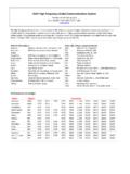
10 Ionosphere layers ..B-6 Table B-3. Regular variations of the ionosphere ..B-7 Table B-4. Irregular variations of the ionosphere ..B-7 Table C-1. Take-off angle versus distance .. C -2 Table C-2. HF antenna selection matrix .. C-4 Table E-1. Two-digit Julian date calendar (regular year) ..E-2 Table E-2. Two-digit Julian date calendar (leap year) ..E-3 Table E-3. Example of world time zone conversion (standard time) ..E-4 Table F-1. Compromised network recovery procedures: compromised transmission encryption keys and key encryption keys .. F-2 Table F-2. Compromised network recovery procedures: compromised transmission encryption keys F-3 Table H-1. Transmitters and transmission range with and without the frequency hopping multiplexer .. H-4 Table I-1. Phonetic alphabet .. I-1 Table I-2. Numerical pronunciation .. I-2 Table I-3. Numerals in combinations .. I-2 Table I-4. Procedure words listed alphabetically .. I -3 Table K-1. AN/PSC-5/C/D, AN/PRC-117F and AN/ARC-231 line of sight interoperability.