Transcription of Audible Alarm Controls LC 10 0 - Pneumercator
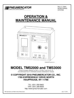
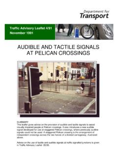
1 Audible Alarm ControlsLC 10 0 0 The LC 1000 series Alarm consoles are designed for use with any tank mounted sensing device that trans-mits an Alarm condition by opening or closing switch contacts. While the Controls are usable with a variety of field sensors, the LC s are optimized for level control . They assure com-plete safety and minimum installation cost by requiring only low current, intrinsically safe wiring between con-sole and tank switch. Housed in a water tight enclosure, the solid state circuitry provides from one (1) to four (4) Alarm channels for monitoring up to four independent sensing points. Bright incandescent Alarm lights and a loud sounding horn warn of Alarm conditions. Dry con-tacts are provided for controlling your external devices such as pumps, valves, or remote Alarm Consoles can monitor multiple tanks High and low level warning lights Audible Alarm with reset button Multiple switches Push button test Intrinsically safe operation of tank mounted sensorsOperationEach Alarm channel transmits a 12 VDC signal to a tank mounted level switch.
2 When the switch senses alevel Alarm condition, the switch transfers and the LC 1000 circuit energizes the Audible horn and in-dicator light. The light will remain on after silencing the horn by pressing the reset button. At any time, an operator may test the Alarm circuit by pressing the test Overfill Alarm RequirementsTypical ApplicationFile No. Level control SystemsAudible Alarm ControlsLC 10 0 0 SpecificationsPower Input 120 VAC 10%, 60 HzFuse .10 AMP, AG-SLO BLOP ower to Field SensorLow electrical energy; 12 VDC at 15mAprovided by control unit to each sensorswitch. Safe for Class I, Division 1, Groups A,B, C, D; Class II Division 1, Groups E, Relay OutputDry switch contact SPDT per point, rated 3 AMPS at 120 VAC; selectable either normallyopen or normally TimeTypically 1/2 second. Automatic horn silenceoption, adjustable 30 seconds to 3 light indicates Alarm conditionHorn signals Audible Alarm 85dB button silences alarmTest button tests Alarm circuitsTemperature-40 F to 160 F (-40 C to 71 C)EnclosureNEMA 4-weatherproof standardInstallationWall mount standardWeight6 lb ( kg) approx.
3 Small case11 lb (5 kg) approx. large caseSensor CableStandard 2 conductor #18 AWGUp to 5000 feet (1524 m) (by customer)Sample SpecificationsProvide and install for each tank A _____ (high/low) level/overfill prevention Alarm / control console. Console should display a visual indication of Alarm condition and include an Audible Alarm horn with reset button. Visual indication should remain on until Alarm condition is corrected. A test button on the Alarm console should be provided to function test Audible and visual Alarm circuits. The console should provide a SPDT switch output, rated 3 AMPS at 120 VAC for controlling external devices. Electrical circuitry to tank mounted process sensors should be listed intrinsically safe for hazardous areas. The sensor wiring must be run in separate conduit containing no line console should consist of solid state electronic circuitry operated from 120 VAC power, housed in a weatherproof enclosure, model _____(see model number table) manufactured by the Pneumercator Co.
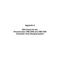
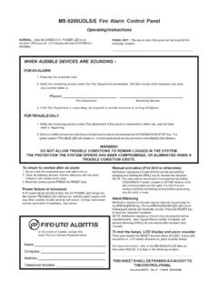
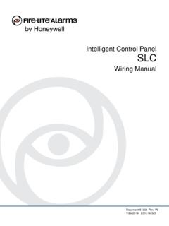
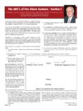
4 , Hauppauge, NY No. Level control SystemsDistributed by:B-LC1000 Printed in 04/13 Pneumercator COMPANY, Expressway Drive North, Hauppauge, NY 11788(631) 293-8450 FAX (631) 293-8533 PartNumberLC1001LC1002LC1003LC1004 Single PointTwo PointsThree PointsFour PointsLC1 SALC2 SALC3 SALC4 SASpecifications subject to change without Level control SystemsMODEL LC1000 Pneumercator Co., Inc. Farmingdale, 21 KNATHGIHRESETTEST2-POINTDIMENSIONS ARE IN INCHESOVERALL DEPTH = INCHESPNEUMERCATORL iquid Level control SystemsMODEL LC1000 Pneumercator Co., Inc. Farmingdale, Level control SystemsMODEL LC1000 Pneumercator Co., Inc. Farmingdale, .313 MTG HOLESANNUNCIATORSILENCE SWITCHBOTTOM OF CASE4 HOLES FOR 1/2" CONDUIT HUBSWARNING LIGHTAVAILABLE FORHIGH OR LOWFUNCTIONSPNEUMERCATORNAMEPLATECIRCUIT TESTSWITCHPNEUMERCATORL iquid Level control SystemsMODEL LC1000 Pneumercator Co.
5 , Inc. Farmingdale, OF CASE2 HOLES FOR1/2" CONDUIT HUBSD imensions