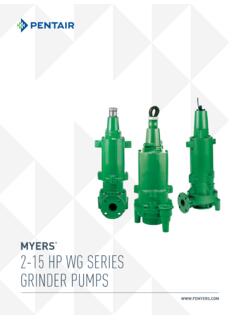
Transcription of AURORA cp boss CONSTANT PRESSURE BOOSTER SYSTEMS
1 AURORA cp bossCONSTANT PRESSURE BOOSTER PRESSURE BOOSTER SYSTEMSAURORA cp bossConstant PRESSURE BOOSTER SystemsCapacities to 1200 GPM ( M3 /HR)Pressures to 175 psi (123 M)Potable Water ApplicationConstant PRESSURE Pumping IntroductionCP Boss, AURORA s packaged CONSTANT PRESSURE BOOSTER SYSTEMS are designed to meet the ever increasing demand of variable flows in high-rise, commercial, municipal and industrial buildings. These PLC based SYSTEMS are available in horizontal and vertical configurations. Easy to select and install, pre-engineered duplex and triplex units are available for quick delivery.
2 Each system is performance tested for trouble free operation and ease of installation and SelectorStandard Features UL labeled PRESSURE sensing control panel PLC pump sequence controller Duplex or triplex Vertical or horizontal configurations Cast iron, bronze fitted centrifugal pumps High efficiency motors Steel manifolds Complete factory test Pilot operated PRESSURE regulating valves Maximum PRESSURE up to 175 psi, maximum flows up to 1200 GPM Single source responsibilityOptional Features ASME rated steel bladder tank Galvanized, copper or stainless steel headers Vertical stackable pumps Special control panelsPackaged CONSTANT PRESSURE BOOSTER SYSTEMS described in this bulletin are used in offices and high rise PRESSURE BOOSTER SYSTEMSA.
3 Completely Assembled and prewired for easy PRESSURE Sensing Control Panel The programmable controller incorporated into the UL listed NEMA 1 Control Panel readily allows for the addition of optional control functions and alarm SYSTEMS feature AURORA 340 Series centrifugal end- suction pumps in bronze-fitted construction. Bronze shaft sleeve prevents shaft wear and extends the entire length of the seal box. Sleeve and impeller screw are sealed by o-ring gaskets to eliminate corrosion of the shaft by the liquid being pumped.
4 Mechanical seal has carbon against a ceramic face for optimum water performance. Long life is also assured with 303 stainless steel metal parts and Buna-N elastomers. Back pull-out design simplifies disassembly. suction and discharge piping is not disturbed and /or misaligned when servicing pumps. Standard motor approved by a joint NEMA and the Hydraulic Institute provides low noise level pump operation. Carbon steel motor shaft is designed for minimum deflection not to exceed.
5 002 at seal faces when at maximum load. Bearings are selected for a long service life under severe operating conditions. Dynamically balanced impeller is keyed to the shaft. Quality controlled manufacturing process assures consistently high performance. Enclosed design provides highest efficiency and is vacuum cast. A case wear ring prevents wear on the pump casing and is easily and inexpensively replaced as PRESSURE Reducing valves automatically reduce higher inlet PRESSURE to a CONSTANT downstream PRESSURE regardless of changing flow rate or inlet PRESSURE .
6 Pilot control settings are readily accessable and are easy to adjust. Return flow is prevented through built in check valves. For some applications where CONSTANT discharge PRESSURE is not critical or where suction PRESSURE is relatively CONSTANT as with a reservoir, silent check valves may be substituted for PRESSURE reducing PRESSURE Gauges are located on suction and discharge Steel Manifolds are painted AURORA blue for corrosion resistance and to meet various local codes. Flanged connections provide easy installation.
7 All piping is schedule Welded Groutable Steel Base provides complete support while still allowing the unit to be readily maneuvered for Full-Port Ball Valves provided on each pump suction and discharge branch will allow individual pumps to be serviced without interrupted Thermal Relief Valve is installed in pump casing to prevent overheating and pump failure. The valve will automatically sense the rise in temperature and discharge some of the hot fluid causing the cooler fluid to enter the casing and the valve will then Hydropneumatic PRESSURE Tank (not illustrated) can be optionally provided to maintain system PRESSURE during periods of low demand.
8 Depending on specific application, the tank can be located adjacent to the system in the equipment room, remotely located, or mounted with the system on the common FeaturesABCDEFGHI4 CONSTANT PRESSURE BOOSTER SYSTEMSPump and System SelectionAll packaged BOOSTER SYSTEMS have a desired discharge PRESSURE and a given suction PRESSURE from the city water system, or from a suction tank. Individual pump boost PRESSURE is usually the system boost plus the friction losses within the BOOSTER system pipe, fittings, and PRESSURE reducing valves. Individual pump flow is usually two equal sized pumps on a duplex system, and a percentage such as 20% + 40% + 40% = 100% for a triplex system.
9 Determine the system flow and boost as well as individual pump flow and ) Total system flow in GPM_____ Determine required flow per pump in GPM (Total system flow No. of pumps) P1_____ P1_____ P1_____2) Determine system manifold size 0 250 GPM 3 0 450 GPM 4 0 1200 GPM 6 3) Determine pump head (TDH) A: Desired PRESSURE at system discharge manifold _____psig B: Minimum pump suction pressure_____psig (City supply or tank) Determine PRV size(s) C: Determine Flow Losses based on PRV Size_____Ft.
10 (See Chart Below) Calculate Required Pump TDH: [ A - B ] x + C [ (A)____psig -____(B) psig ] x +____(C) ft. =____ft. Indivdual Pump Duty Points: P1 _____GPM TDH P2 _____GPM TDH P3 _____GPM TDH4) Select required pumps and motors using AURORA H2 Optimize or the current AURORA Pump catalogPUMP FLOW50 GPM70 GPM110 GPM150 GPM275 GPM400 GPMPRV SIZE1-1/4 1-1/2 2 2-1/2 3 4 PRESSURE BOOSTER SYSTEMSP erformance Data 6 CONSTANT PRESSURE BOOSTER SYSTEMSM odel DiagramsVERTICAL DUPLEXVERTICAL PRESSURE BOOSTER SYSTEMSM odel DiagramsHORIZONTAL DUPLEXHORIZONTAL TRIPLEXHYDRAULIC 1 9 I N S T I T U T E 1 7 ISO 9001 REGISTERED QUALITY SYSTEM 800 AIRPORT ROAD, NORTH AURORA .