Transcription of AUTO TRANS DIAGNOSIS - AW-40 - Stefan Caunter
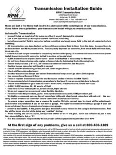
1 auto TRANS DIAGNOSIS - AW-40 1994 Volvo 960 AUTOMATIC transmissions Volvo AW-40 Series Testing & DIAGNOSIS APPLICATION & LABOR TIMESAPPLICATION & LABOR TIMES Vehicle Labor TimesApplication (1) R & I (2) Overhaul Series960 .. AW-40 (1) - Removal and installation of transmission from vehicle chassis.(2) - Bench overhaul time for transmission. DOES NOT include removal and installation. CAUTION: Vehicle is equipped with a Supplemental Restraint System (SAS). When servicing vehicle, use care to avoid accidental air bag deployment. SRS-related components are located in steering column, center console, instrument panel and lower panel on instrument panel. DO NOT use electrical test equipment on these circuits. If may be necessary to deactivate SRS before servicing components. See AIR BAG SERVICING article in APPLICATIONS & IDENTIFICATION section. Refer to the following: * 1992 models, see: AIR BAG RESTRAINT SYSTEM * 1993 models, see: AIR BAG RESTRAINT SYSTEM * 1994 models, see: AIR BAG RESTRAINT SYSTEM IDENTIFICATION Transmission can be identified by identification plateattached at right rear of transmission case.
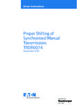
2 Identification platecontains transmission model, year of manufacture and transmission partnumber. See Fig. 1. Transmission model number may be AW30-40LE 1: Locating Transmission Identification Plate InformationCourtesy of Volvo Cars of North America. DESCRIPTION Transmission is a 4-speed overdrive electronically controlledautomatic transmission. Transmission consists of lock-up torqueconverter, oil pump, 3 planetary gear sets, clutch and brake units,accumulator pistons, valve body and 4 electronic valve body solenoids. Valve body with solenoids and Transmission Control Module(TCM) are used for controlling transmission operation. Solenoids arecontrolled by TCM. TCM receives input signals from various components todetermine transmission shift points and torque converter consist of mode selector switch, throttle position sensor,transmission speed (RPM) sensor, gear position sensor, transmissionoil temperature sensor, brake switch and kickdown switch.
3 See Fig. 2. Transmission is equipped with a mode selector switch. Switchis used for normal, high performance and winter driving is also equipped with a shift lock and key interlocksystem. Shift lock system prevents shift lever from being moved fromPark position unless brake pedal is applied. In case of malfunction,shift lever can be released by depressing shift lock override button,located near shift lever. Key interlock system prevents ignitionswitch from being moved from ACC to LOCK position unless shift leveris in Park 2: Locating Transmission ComponentsCourtesy of Volvo Cars of North America. OPERATION BRAKE SWITCH Brake switch is an input device mounted above the brakepedal. When brake pedal is applied, brake switch delivers an inputsignal to the TCM. TCM uses input signal to control No. 3 solenoid fortorque converter lock-up. GEAR POSITION SENSORNOTE: Gear position sensor may also be referred to as neutral safety switch. Gear position sensor is an input device mounted on thetransmission manual valve shaft.
4 Sensor delivers an input signal toTCM, indicating transmission manual valve gear position. KEY INTERLOCK SYSTEM With ignition key in ignition switch, place shift lever into"P" position. Ensure ignition key can be installed and removed fromignition switch with ease. If key is difficult to remove, keyinterlock cable is too short. Adjust cable as necessary. Move shiftlever to position other than Park. Ignition key should not beremovable from ignition switch. If key can be removed, cable is toolong. Adjust cable as necessary. KICKDOWN SWITCH Kickdown switch, located at firewall on accelerator cable,sends input signal to TCM when accelerator pedal is fully uses input signal for controlling transmission downshifting andtorque converter lock-up. MODE SELECTOR SWITCH Mode selector switch, located to left of shift lever, has 3different modes which effect transmission shift points. Input signalfrom mode selector switch is sent to TCM. TCM uses input signal forcontrolling transmission shifting and torque converter lock-up.
5 "E" (Economy) mode, is for normal driving and provides earlyupshifts combined with lock-up as often as possible for top 3 line pressure is modulated to provide smooth gearengagement. In "S" (Sport) mode, transmission shift points are designedto provide the highest possible performance. Under normalacceleration, transmission shifts occur the same as in economy increased acceleration, TCM selects shift and lock-up pointsfor best possible performance. "W" (Winter) mode prevents wheel spin on slippery starts out in high gear. When "W" mode is selected,warning light on dash is illuminated. This mode may also be used whendriver wants to control gear selection. OIL TEMPERATURE SENSOR Oil temperature sensor, located on right side oftransmission, forward of gear position sensor, measures transmissionfluid temperature and delivers an input signal to TCM. TCM uses inputsignal for controlling transmission shifting and torque converterlock-up. SHIFT LOCK OVERRIDE FUNCTION Move shift lever to "P" position and turn ignition key to (I)or (II) position.
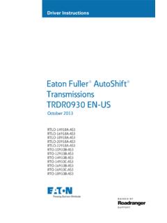
6 Press override button. Shift lever should move from"P" position. Return shift lever to "P" position and remove ignitionkey. Press override button. Shift lever should not move from "P"position. Override function should operate only when ignition key isin (I) or (II) position. TRANSMISSION CONTROL MODULE (TCM) TCM is located under instrument panel, to right of steeringcolumn. See Fig. 3. TCM determines shift points and torque converterlock-up timing based on input signals received from variouscomponents. Components consist of mode selector switch, throttleposition sensor, transmission speed (RPM) sensor, gear positionsensor, transmission oil temperature sensor, brake switch and kickdownswitch. TCM contains a self-diagnostic system which stores aDiagnostic Trouble Code (DTC). If a transmission problem exists,DTC(s) can be retrieved to determine transmission problem 3: Locating Transmission Control Module (TCM)Courtesy of Volvo Cars of North America. TRANSMISSION SPEED (RPM) SENSOR Electromagnetic RPM sensor, mounted in transmission housing,is activated by a toothed impulse wheel.
7 Sensor is an input devicewhich delivers an RPM signal to the TCM. By comparing transmission RPMand vehicle speed, TCM calculates torque converter slippage. THROTTLE POSITION (TP) SENSOR Throttle position sensor, mounted on throttle body,determines throttle position and delivers an input signal to TCM. TCMuses input signal for controlling transmission upshifts and torqueconverter lock-up. VALVE BODY SOLENOIDS Valve body solenoids, mounted on the valve body, are outputdevices controlled by signals received from the TCM. The No. 1 and solenoids are used to control transmission shifting. No. 3 solenoidis used to control torque converter lock-up. No. 4 solenoid is used tocontrol transmission line pressure. For valve body solenoid usage, seeVALVE BODY SOLENOID APPLICATION BODY SOLENOID APPLICATION (1) Shift Lever No. 1 No. 2 Position Solenoid Solenoid"D" (Drive) 1st .. ON .. OFF 2nd.
8 ON .. ON 3rd .. OFF .. ON 4th .. OFF .. OFF"3" 1st .. ON .. OFF 2nd .. ON .. ON 3rd .. OFF .. ON"L" 1st .. ON .. OFF 2nd .. ON .. ON"R" (Reverse) .. ON .. OFF"N" Or "P" .. ON .. OFF(1) - Valve body contains 4 solenoids. No. 1 and No. 2 solenoids are used to control transmission shifts. No. 3 solenoid is used to control torque converter lock-up. No. 4 solenoid is used to control line pressure. LUBRICATION & ADJUSTMENTS See the TRANSMISSION SERVICING - A/T article in the AUTOMATICTRANS SERVICING section. TROUBLE SHOOTING Preliminary Checks Ensure fluid level is correct. Inspect throttle cable,kickdown cable and gear position sensor. Check idle speed RPM andadjust as : Manufacturer recommends transmission assembly replacement only. Manufacturer does not provide mechanical trouble shooting or overhaul information. TESTING ROAD TEST "D" & "3" Position 1) Engine and transmission must be at normal operatingtemperature.
9 Shift transmission into "D" position. Set mode selectorswitch to "E" position. Test drive vehicle and ensure all upshifts anddownshifts occur at specified speeds. See SHIFT SPEED SPECIFICATIONS table. 2) Ensure lock-up occurs at appropriate speeds. See LOCK-UPSPEED SPECIFICATIONS table. Lightly depress accelerator. If excessiveincrease in engine RPM exists, lock-up did not : Lock-up in 2nd gear occurs when transmission oil temperature exceeds 257 F (125 C) on AW30-40 transmission or 239 F (115 C) on AW30-43 transmission. Lock-up in 3rd gear occurs when transmission oil temperature exceeds 140 F (60 C). Lock-up in 4th gear occurs when transmission oil temperature exceeds 86 F (30 C). "L" Position While driving vehicle in "L" position, check for failure toupshift to 2nd gear. Check engine braking effect when acceleratorpedal is released. "R" Position Shift vehicle into "R" position. Accelerate vehicle and checkfor transmission slippage.
10 "P" Position Stop vehicle on incline of 5 degrees or steeper. Shiftvehicle into "P" position and release parking brake. Ensure parkingpawl prevents vehicle from moving. TIME LAG TEST 1) Engine and transmission must be at normal operatingtemperature. Start engine and ensure idle RPM is within specificationwith A/C off. Apply service and parking brakes. Using stop watch,measure time until engagement shock is felt when shift lever isshifted from "N" to "D" position. 2) Allow one minute intervals between tests. Perform timemeasurement several times and calculate average time. Time should beless than .7 seconds. Repeat test procedure to test time lag whenshift lever is shifted from "N" to "R" position. Time lag should beless than seconds. If test time is not as described, checktransmission line pressure. See HYDRAULIC PRESSURE SPEED SPECIFICATIONS (1) Application MPHAW30-40 Economy Mode 1st-2nd .. 25 2nd-3rd.