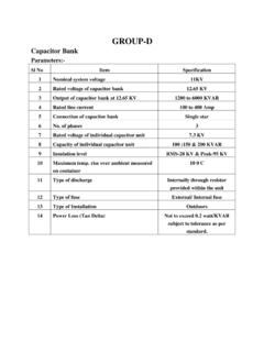
Transcription of Automatic Remote Controlled Antenna Tuner for Balanced …
1 Go back with the Arrow Button in the Explorer Menu RF Communication Electronics Klaus Bemmerer Niendorf-Middeldor 11 23769 Fehmarn GERMANY Int l Phone +49 4371 869145 Int l Fax +49 4371 869154 eMail Site Automatic Remote Controlled Antenna Tuner for Balanced and Unbalanced HF Antennas Model AT-502 Antenna Tuner System AT-502 Description This Tuner is designed to match remotely, both Balanced and unbalanced HF antennas. This unit features Automatic selection of Tuner settings based upon transmitted frequency.
2 Unique to this Tuner , no special cabling or adapters are required. The operator simply transmits into the Antenna and the Tuner detects the transmitted frequency and selects the correct settings from memory. The Ham bands are divided into 85 operator programmable memory locations. There are two banks of 85 memory locations that are user selectable. To best utilize this capability, a new Antenna switch (ASU-502) has been designed as an accessory to the AT- 502 Tuner . This switch is activated at the AT- 502 by the ANT1/ANT2 switch located on the front panel of the controller.
3 This enables the operator to have complete Tuner control for two different antennas. It will handle 200 watts of SSB or CW power, and it can be used in either Automatic or manual mode. The matching circuit consists of a remotely tuned Balanced circuit (no balun at Tuner output!). An internal jumper selects the balance or un- Balanced configuration. This jumper Go back with the Arrow Button in the Explorer Menu Page 2 of 6 can be remotely Controlled by the ASU-502 Antenna Switch. This unit features lightning protection and is built in a weather- proof UV resistant plastic cabinet.
4 The Control Cabinet contains the tuning controls, memory bank and Antenna selection, Automatic or Manual switching and a display that indicates the memory bank in use, the frequency range as well as the span, and the Tuner settings. Refer to the Tuner System Block Diagram in this document for system inter-connect information. Main Features Automated Tuner control based on transmitted frequency. No special cabling. Remote Matching of Balanced or unbalanced antennas within the Amateur bands to 30 MHz.
5 True Balanced Pi Tuner to match dipoles, loops, inverted Vee s etc. (no lossy balun between Tuner and Antenna ) Un- Balanced Pi Tuner to match any un- Balanced Antenna Antenna Switch ASU-502 is an option to allow 2 different antennas either Balanced or unbalanced or mixed to be selected remotely LC Display at the Controller for indication of Remote matching values of the -filter, the memory location and the number of the Antenna in use as well as other occasional service information.
6 Automatic choice of the Tuner settings Controlled by the transmitting frequency Alternative manual control of the Remote Tuner Built in lightning protection Built in over voltage protection. DC power feed from station s power supply V, Amps. Tuner System Block Diagram TransceiverSWR MeterControl CableCoax 50 OhmAT-502 Automatic ControllerHF-SensorRF ProbeAT-502 TunerAntennamax. 30m (100 ft)RF Outdoor UnitANT1 ANT2 Antenna Selection BoxASB-502(0ptional)Go back with the Arrow Button in the Explorer Menu Page 3 of 6 Technical Description RF Unit: The RF Unit is housed in a weatherproof and UV resistant plastic cabinet.
7 There are two ceramic feed-through insulators where a Balanced Antenna or a Balanced feeder line can be attached The LC network is a Balanced Pi. At the front end of the network there is a balun transformer that matches the un- Balanced coax cable to the Balanced Tuner elements. This is the only place where the impedance of the system is purely resistive (when matched) and is the ideal place for the Balun. The regular station SWR meter is used as an indicator to match the Antenna .
8 The capacitors at the input are switched in 256 steps of 17 pF per step. The capacitors at output are switched in 256 steps of pF per step. The inductors are switched in 64 steps increasing exponentially. Switching is done by power relays. With the circuit components used it is possible to match very short antennas up to an unlimited Antenna length within the RF range from to 30 MHz. When matching an unbalanced Antenna , one insulator is used for the hot side or centre conductor of the Antenna ; the second insulator is used for shield or ground.
9 The accessory Antenna switch (ASU-502) can be plugged into the Tuner unit when two antennas are used. This will configure the Tuner for Balanced or un- Balanced operation and select the appropriate Antenna . The selection is done from the Controller unit ANT1/ANT2 switch.. Interior view of the RF unit looking at the inductor board, the board with the capacitor banks is located below Go back with the Arrow Button in the Explorer Menu Page 4 of 6 Controller Unit: Antenna matches can be stored for 2 different antennas into 2 separate memory banks.
10 Each bank has 85 memory locations. Each memory location is a fraction of an amateur band. Refer to the technical section for the fractional segments for each band. As shown in the picture below, the upper line of the LCD shows the actual memory location chosen (lower edge frequency 7120 kHz) with its span (30 kHz). The control settings for this frequency are shown in the lower line of the LCD. In the Automatic Mode the memory location and its stored settings is selected by the transmitted input frequency.