Transcription of AUTOMATIC TRANSMISSION (A340E)
1 AT- 1. AUTOMATIC . TRANSMISSION (A340E). Page DESCRIPTION ..AT-2. TROUBLESHOOTING .. AT-9. Basic Troubleshooting .. AT-9. General Troubleshooting .. AT-10. Operating Mechanism for Each Gear .. AT-12. Diagnosis System .. AT-13. Preliminary Check .. AT-18. Manual Shifting Test .. AT-20. Electronic Control System .. AT-21. Mechanical System Tests .. AT-32. AUTOMATIC Shift Schedule .. AT-40. Neutral Start Switch .. AT-41. ON-VEHICLE REPAIR .. AT-42. Valve Body Parking Lock Pawl Extension Housing Speedometer Driven Gear REMOVAL AND INSTALLATION OF. TRANSMISSION .. AT-43. TORQUE CONVERTER AND DRIVE PLATE .. AT-45. REMOVAL OF COMPONENT PARTS .. AT-46. COMPONENT PARTS .. AT-65. General Notes .. Oil Pump .. Overdrive Planetary Gear. Overdrive Direct Clutch and Overdrive One-Way Clutch .. Overdrive Brake .. Direct Clutch .. Forward Clutch .. Second Coast Brake .. Front Planetary Gear.
2 Planetary Sun Gear and No . 1 One-Way Clutch .. AT-96. Second Brake .. AT- 1 0 0. First and Reverse Brake .. AT- 1 0 3. Rear Planetary Gear. No . 2 One-way Clutch and Output Shaft .. AT- 1 0 4. Valve Body .. AT- 1 0 9. Disassembly of Valve Body .. AT- 1 0 9. Upper Valve Body .. AT-111. Lower Valve Body .. AT-1 1 4. Assembly of Valve Body .. AT-1 1 7. TRANSMISSION Case .. AT- 1 1 8. Extension Housing .. AT-1 1 8. INSTALLATION OF COMPONENT PARTS .. AT-119. SHIFT LOCK SYSTEM .. AT-142. AT-2 AUTOMATIC TRANSMISSION - Description DESCRIPTION. GENERAL. The A 3 4 0 E is a 4-speed, Electronic Controlled TRANSMISSION (hereafter called ECT) developed for use w i t h high-performance engines such as t h e 7M-GE and 7M-GTE. A lock-up mechanism is built into t h e torque converter. The A 3 4 0 E TRANSMISSION is mainly composed of the torque converter, t h e overdrive (hereafter called O I D ).
3 Planetary gear unit, 3-speed planetary gear unit, the hydraulic control system and the electronic control system. Torque Converter Rear Planetary Hydraulic Control Unit AUTOMATIC TRANSMISSION - Description AT-3. Outline of ECT. The conventional AUTOMATIC TRANSMISSION operates by mechanically converting vehicle speed into governor pressure, and throttle opening into throttle pressure, and using these hydraulic pressures to control the operation of the clutches and brakes in the planetary gear unit, thus controlling the timing of up-shift and down-shift of the TRANSMISSION . This is called the "hydraulic control method.". In the case of the ECT, on the other hand, sensors electronically sense the speed of the vehicle and the throttle opening and send these information t o the electronic controlled unit (hereafter called ECU) in the form of electrical signals. The ECU then controls the operation of the clutches and brakes based on these data, thus controlling the timing of the shift points.
4 SHIFT CONTROL. Hydraulic Controlled TRANSMISSION Shifting in the fully hydraulic controlled AUTOMATIC TRANSMISSION is carried out by the hydraulic con- trol unit in the following way: Throttle Valve THROTTLE V A L V E GOVERNOR V A L V E. throttle valve in the hydraulic control unit governor valve generates hydraulic pressure generates hydraulic pressure in proportion t o In proportion t o the speed o f the vehicle; this , the amount that the accelerator pedal is de- pressure (called "governor pressure") acts as a pressed; this pressure (called "throttle pres- vehicle speed "signal" t o the hydraulic control sure") acts as a throttle opening "signal" t o the unit. hydraulic control unit. ---- H Y D R A U L I C CONTROL U N I T. Governor pressure and throttle pressure cause the shift valves in the hydraulic control unit t o operate; the strengths of these pressures con- trol the movements of these valves, and these valves control the fluid passage t o the clutches and brakes in the planetary gear unit, which in turn control the shifting o f the TRANSMISSION .
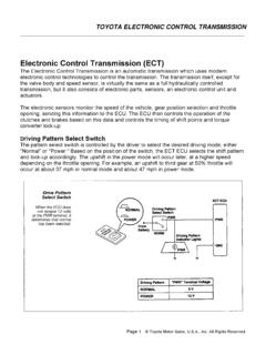
5 AT-4 AUTOMATIC TRANSMISSION - Description ECT. Aside from having an ECU which controls shifting based upon electrical speed and throttle opening signals, the ECT is basically the same as a fully hydraulic controlled AUTOMATIC TRANSMISSION . The ECT controls shifting in the following manner: Signal). r THROTTLE POSITION SENSOR. The throttle opening i s sensed by the throttle ~ o s i t i o nsensor, which sends this data t o the ECU in the form of electrical signals. I. VEHICLE SPEED SENSOR. vehicle speed is sensed by sensor, which sends this data t o the E c u in the form o f electrical signals. - ECU. The ECU determines the shift timing on the basis of the vehicle speed and throttle opening signals, and operates the solenoid valves in the hydraulic control unit, thus controlling the movement o f the shift valves. These valves in turn control the fluid passage t o the clutches and brakes in the planetary gear unit, which control the shifting of the TRANSMISSION .
6 AUTOMATIC TRANSMISSION - Description AT-5. PLANETARY GEAR UNIT. The planetary gear unit is composed of three sets of planetary gears, three clutches w h i c h transmit p o w e r t o the planetary gears, and four brakes and three one-way clutches w h i c h immobilize the planetary carrier and planetary sun gear. Power f r o m t h e engine transmitted the input shaft via t h e torque converter is then transmitted t o the plane- tary gears b y t h e operation of the clutches. B y operation of t h e brakes and one-way clutches, either t h e planetary carrier or the planetary sun gear is immobilized, altering the speed of revolution of the planetary gear unit. Shift change is carried o u t b y altering t h e combination of clutch and brake operation. Each clutch and brake operates by hydraulic pressure; gear position is decided according t o the throttle opening angle and vehicle speed, and shift change automatically occurs.
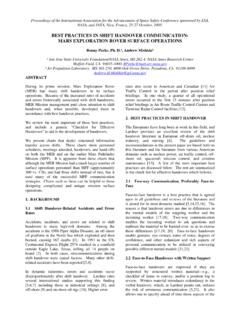
7 \. O/D Direct 2nd Coast Brake ( B 1 ) Forward Clutch 1st & Reverse Clutch (Co). \O/D. Direct "". Brake ( B o ) Clutch (C2). 1 (62). Brake (B3) Rear Planetary Carrier Rear Planetary Ring Gear input ~ h ' a f t Ring Gear AT2157. OPERATION OF EACH ELEMENT. NOMENCLATURE OPERATION. O/D Direct Clutch ( C o ) Connects overdrive sun gear and overdrive carrier O/D Brake ( B o ) Prevents overdrive sun gear from turning either clockwise or counterclockwise O/D One-way Clutch ( F o ) When TRANSMISSION i s being driven by engine, connects overdrive sun gear and over- drive carrier I Forward Clutch (C1) I Connects input shaft and front planetary ring gear I Direct Clutch ( C 2 ) 1 Connects input shaft and front & rear planetary sun gear I. 2nd Coast Brake (B1) Prevents front & rear planetary sun gear from turning either clockwise or counter- clockwise 2nd Brake (62 ) Prevents outer race of F 1 from turning either clockwise or counterclockwise, thus preventing front & rear planetary sun gear from turning counterclockwise 1st & Reverse Brake ( B 3 ) Prevents rear planetary carrier from turning either clockwise or counterclockwise I NO.
8 1 One-way Clutch IF,). I When B2 is operating, prevents front & rear planetary sun gear from turning ~ ~ ~ n t e r ~ l o ~ k ~ i ~ e I. No. 2 One-way Clutch (F2 ) Prevents rear planetary carrier from turning counterclockwise OPERATING CONDITIONS FOR EACH GEAR. (See page AT- 121. AT-6 AUTOMATIC TRANSMISSION - Description HYDRAULIC CONTROL SYSTEM. The hydraulic control system is composed of the oil pump, the valve body, the solenoid valves, and the clutches and brakes, as well as t h e fluid passages w h i c h connect all of these components. Based o n t h e hydraulic pressure created b y the oil pump, the hydraulic control system governs the hydraulic pressure acting o n the torque converter, clutches and brakes in accordance w i t h t h e vehicle driving conditions. There are three solenoid valves o n t h e valve body. These solenoid valves are turned o n and o f f b y signals from the ECU t o operate the shift valves.
9 These shift valves then s w i t c h t h e fluid passages so t h a t fluid goes t o t h e torque converter and planetary gear units. (Except for t h e solenoid valves, t h e hydraulic control system of the ECT is basically the same as that of the fully hydraulic controlled AUTOMATIC TRANSMISSION .). I. I. 1 OIL. - H Y D R A U L I C CONTROL SYSTEM - - PUMP^. r- I. - - V A L V E BODY- Hydr. pressure control -- I. 1. - 1. I. I. I. Fluid passage switching CLUTCHES & BRAKES. -1. i '-, Torque converter I I. I I. I. I. SOLENOID VALVES. i1. I. LINE PRESSURE. Line pressure is t h e m o s t basic and important pressure used in the AUTOMATIC TRANSMISSION , because i t is used t o operate all of the clutches and brakes in the TRANSMISSION . If t h e primary regulator valve does n o t operate correctly, line pressure will be either t o o high or t o o l o w . Line pressure t h a t is t o o high will lead t o shifting shock and consequent engine p o w e r loss due t o the greater effort required of the oil pump; line pressure that is t o o l o w will cause slippage of clutches and brakes, w h i c h will, i n extreme cases, prevent the vehicle f r o m moving.
10 Therefore, if either of these problems are noted, t h e line pressure should be measured t o see if i t is w i t h i n standard. THROTTLE PRESSURE. Throttle pressure is always kept in accordance w i t h t h e opening angle of the engine throttle valve. This throttle pressure acts o n t h e primary regulator valve and, accordingly, line pressure is regulated in response t o the throttle valve opening. In t h e fully hydraulic controlled AUTOMATIC TRANSMISSION , throttle pressure is used for regulating line pressure and as signal pressure for up-shift and down-shift of the TRANSMISSION . In the ECT, however, throttle pressure is used only for regulating line pressure. Consequently, improper adjustment of t h e TRANSMISSION throttle cable m a y result in a line pressure t h a t is t o o high or t o o l o w . This, in turn, will lead t o shifting shock or clutch and brake slippage.