Transcription of Automotive Circuit Protection using ... - Littelfuse
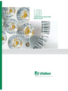
1 1 2019 Littelfuse NoteAutomotive Circuit Protection using Littelfuse Automotive TVS DiodesSafetyAirbagsBattery DisconnectAnti-rolloverStability ControlSeat Belt Pre-tensioningTire Pressure MonitoringHID LightingSeating Controls/MemoryRide ControlTheater LightingClimate ControlNavigation SystemsInfotainment/VideoComfort and ConvenienceEngine ManagementAdaptable SuspensionAdvanced PowertrainsPerformance and EmissionsGas ElectricFuel Cell ElectricDiesel ElectricLi-Ion PolymerUltra-capacitorsHybrid VehiclesFigure 1. Vehicle Systems Subject to Transient Surge HazardsThe designers of Automotive electronics face many technical challenges during the system design process, including designing methods of Protection against a variety of electrical hazards. The three major sources of electrical hazards in these systems are electrostatic discharge (ESD), lightning, and switching loads in power electronics circuits. Overcoming transient surges that can harm the vehicle s electronics is one of the biggest challenges of the design ChallengeThe SolutionNote: For 48V power system with high power surge rating, welcome to contact Littelfuse for technical support and application test) Protecting Automotive electronics includes eliminating transient surges that can damage the control units, infotainment electronics, sensors, fuel injectors, valves, motors, 12/24/42/48 volts powertrains, and hydrolytic controllers, do Littelfuse Transient Voltage Suppression (TVS) Diodes Protect?
2 As shown in Figure 1, Littelfuse TVS diodes provide Protection for four main categories of vehicle systems: safety, performance and emissions, comfort and convenience, and hybrid modern Automotive designs, all on-board electronics are connected to the battery and the alternator. As indicated in Figure 2, the output of the alternator is unstable and requires further conditioning before it can be used to power the vehicle s other systems. Currently, most of the alternators have zener diodes to protect against load dump surges; however, these are still not sufficient. During the powering or switching of inductive loads, the battery is disconnected, so that unwanted spikes or transients are generated. If left uncorrected, these transients would be transmitted along the power line, causing individual electronics and sensors to malfunction or permanently damaging the vehicle s electronic system, affecting overall Note 2020 Littelfuse 2.
3 The Alternator Causes Most of the Transients In a Vehicle s Electrical MotorBAT T+Alternator/Regulator Assembly(Actual Circuit is fully wave rectified) Automotive Transient Surge (Not ESD) StandardLittelfuse is a leading provider of TPSMF4L, TPSMB, TPSMA6L, TPSMC, TPSMD, TP6KE, , TP5KP, SZSMF, SZ1 SMA, SZ1 SMB, SZP6 SMB, SZ1 SMC, , SLD, SLD5S, SLD6S, and SLD8S Series. TVS Diodes which can provide secondary transient voltage Protection for sensitive electronics from transients induced by load dump and other transient voltage events. These series offer superior electrical performance in a small footprint package, allowing designers to upgrade their Circuit Protection without altering their existing design footprint or to provide more robust Protection in new Circuit dump Protection requires high energy TVS diodes in the 12 and 24 volt system. For more information on load dump Protection , visit Automotive market has major two standards that outline Protection against transient surges: JASO and ISO7637-2 (Surge) test for the Japanese, American, and international markets.
4 JASO A-1 outlines test conditions for 14 volt vehicle systems; JASO D-1 outlines test conditions for 27 volt vehicles. The following test standards are international and American test standards, which include the load dump, switching transients and ESD Jump Start85V Noise120V Load DumpNominal14V6V CrankFigure 3a: Surge Wave of Different Pulses & Its MagnitudeMore Information on the ISO7637-2 Pulses:International Standard ISO7637-2: Applies to road vehicles-electrical disturbance by conduction and couplingUSA National Standard: SAE (Society of Automotive Engineers) J1113 GM 9105, ES-F2af-1316-AA Ford (Visteon) Automotive EMC Transition Requirements Pulse 1- Interruption of inductive load refers to disconnection of the power supply from an inductive load while the device under test (DUT) is in parallel with the inductive load Pulse 2 - Interruption of series inductive load refers to the interruption of current and causes load switching Pulse 3 - Switching spikes 3a negative transient burst 3b positive transient burst Refers to the unwanted transients in the switching events Pulse 4 - Starter crank refers battery voltage drop during motor start.
5 This always happens in cold weather Pulse 5 - Load dump refers to the disconnection of the vehicle battery from the alternator while the battery is being charged. Pulse 6 - Ignition coil interruption Pulse 7 - Alternator field decayPulse 1, 2, 3a, 3b, 5 - Related to high voltage transient getting into the supply line; Pulse 4 defines minimum battery voltage. Refer to Figure 3a and Table 13 Application Note 2020 Littelfuse s tPulseTest Levels (12V System)Min. No. of Pulsesor Test TimeI 75V 100V5000 pulses2a--+37V+112 V5000 pulses2b--+10 V+10 V10 pulses3a-- 112 V 220V1 hour3b--+75 V+15 0 V1 hour5a--+65V+87V1 pulse5b--+65V+87V1 pulseTe s tPulseTest Levels (24V System)Min. No. of Pulsesor Test TimeI 300V 600V5000 pulses2a--+37V+112 V5000 pulses2b--+20V+20V10 pulses3a-- 150V 300V1 hour3b--+15 0 V+300V1 hour5a--+12 3 V+173V1 pulse5b--+12 3 V173V1 pulse Pulse 1 is a transient caused by battery supply disconnection from inductive loads.
6 Pulse 2a simulates transients due to sudden interruption of currents in a device connected in parallel with the DUT due to the inductance of the wiring harness. Pulse 2b simulates transients from DC motors acting as generators after the ignition is switched off. Pulse 3a and 3b are switching transients. Pulse 5a and 5b are load dump transients. 5b clamp voltage Us* is defined by different car manufacturers. The former levels I and II were deleted because they do not ensure sufficient immunity in road vehicles. Four performance levels for each pulse Different o/c voltage Negative and positive Pulse duration - 400ms Single and burst TVS Protection and its operation modeTable 1: ISO7637-2 Test Levels on Each Pulse (12 Volts) Automotive Environment Test LevelsTable 2: ISO7637-2 Test Levels on Each Pulse (24 Volts)Results of Littelfuse Automotive TVS Diode in ISO7637-2 Surge TestTable 1a & 1b summarizes the compliance of each level of the ISO7637-2 surge test in 12 and 24 volt power systems when using various Littelfuse Automotive TVS Diode series.
7 Series TPSMF4L, TPSMA6L, TPSMB, TP6KE, TPSMC, TPSMD, SZSMF, SZ1 SMA, SZ1 SMB, SZP6 SMB, SZ1 SMC and feature pulse power ratings from 400W to 3000W. TP6KE series is a through-hole TVS while the rest are surface mount. These devices help the power system pass the different surge tests (1, 2a, 2b, 3a, 3b, 5a and 5b) operationally as specified by ISO7637-2. Referred to the table 12 volt system below, only if the alternator Ri value is higher than , TPSMD series TVS can then be used to pass the higher energy 5a surge. If Ri value (Altenator internal resistance) is lower than , then the higher power TVS such as SLD, SLD5S, SLD6S or SLD8S series are suggested used for such design. For the 24 volt car power system surge compliance, refer to the 24 volt system results Series12V SystemLevel 3 Level 412a2b3a3b5a12a2b3a3b5a 75V+37V+10V 112V+75V+65V 100V+112V+10V 220V+150V+87 VTPSMF4L/ SZSMFPassPassPassPassPass-PassPassPassPa ssPass- TPSMA6L/ SZ1 SMAPassPassPassPassPass-PassPassPassPass Pass-TPSMB/ SZ1 SMB / SZP6 SMBPassPassPassPassPass-PassPassPassPass Pass-TPSMC/ SZ1 SMC / 1a.
8 Littelfuse Automotive TVS Diode Series Compliance with Various Surge Levels in 12 & 24 volt Powertrains4 Application Note 2020 Littelfuse Series24 Volt SystemLevel 3 Level 412a2b3a3b5a12a2b3a3b5a 300V+37V+20V 150V+150V+123V 600V+112V+20V 300V+300V+173 VTPSMF4L/ SZSMFPassPassPassPassPass-PassPassPassPa ssPass- TPSMA6L/ SZ1 SMAPassPassPassPassPass-PassPassPassPass Pass-TPSMB/ SZ1 SMB / SZP6 SMBPassPassPassPassPass-PassPassPassPass Pass-TPSMC/ SZ1 SMC / PassPassPassPassPassPassConditional PassSLD5S/SLD6S/SLD8 SPassPassPassPassPassConditional PassPassPassPassPassPassConditional PassTable 1b: Littelfuse Automotive TVS Diode Series Compliance with Various Surge Levels in 24 volt PowertrainsAs shown in Figure 3b, the TVS diode TPSMA6L15A is placed before the ECU, sensors, airbag controllers, motor, etc. When the alternator provides power to the electronics, the TVS diode will protect against unwanted transients while allowing DC operating voltage of 12 - 14 volts to the electronic most popular communication bus standards currently are the CAN and LIN bus (Control Area Network) is a vehicle bus standard designed to allow microcontrollers and devices to communicate with each other within a vehicle with no need for a host bus is a message-based protocol, designed specifically for Automotive applications but now also used in other areas, such as aerospace, industrial automation, and medical popular high-speed CAN bus protocol is ISO11898-2, where this differential protocol is good for high-speed ( Mbps) and medium-speed (125 Kbps) applications in harsh environmentsThe ISO11898-2 bus consists of the CAN_H and CAN_L data lines and a common ground signal.
9 It has 12 and 24 volt systems with different bus LIN (Local Interconnect Network) bus standard is a serial network protocol used for communication between components in vehicles. As the technologies and the facilities implemented in vehicles grew, a need arose for a cheap serial network because the CAN bus was too expensive to implement for every component in the car. European car manufacturers started using different serial communication topologies, which led to compatibility first fully implemented version of the new LIN specification (LIN version ) was published in November 2002. In September 2003, version was introduced to expand its capabilities and provide for additional diagnostics features. LIN may also be used over the vehicle s battery power-line with a special DC-LIN transceiver, which is common in today s Automotive , Airbag, Motor, Infotainment, 3b: TVS Diode Used as a Shunt/Transient Surge Protector for Various Car SystemsAutomotive Bus Protection5 Application Note 2020 Littelfuse CANP hysical Layer SpecificationI S O 118 9 8 - 2 FeaturesHigh speed differential bus, good noise immunityPopular ApplicationsAutomotive and industrial controlsTransmission Mbits/s @ 40 meters 125 kbits/s @ 500 metersCableTwisted or parallel pair wires, shielded or unshielded cableTermination Resistance120 W resistors located at each end of the busMin/Max Bus Voltage12 V System: +16 V24 V System: +32 VMin/Max Common Mode Bus VoltageCAN_L: (min)/+ V (nom)CAN_H: (nom)/+ V (max)Table 2.
10 High-Speed CAN SpecificationsApplication SegmentsSpecific LIN Application ExamplesRoofSensor, light sensor, light control, sun roofSteering WheelCruise control, wiper, turning light, climate control, radioSeatSeat position motors, occupant sensors, control panelEngineSensors, small motorsClimateSmall motors, control panelDoorMirror, central ECU, mirror switch, window lift, seat control switch, door lockTable 3: LIN Bus ApplicationsDifferences between CAN and LIN Bus ApplicationsControl Area Network (CAN) systems handle everything from power steering to the critical drive-train communications between the engine computer and the transmission. Local Interconnect Network (LIN) systems handle simple electromechanical functions, such as moving the power seats and toggling the cruise to CAN/LIN Busses in the Automotive WorldBecause CAN/LIN busses are two-wire communication busses for various control and monitor functions inside the car, they have a high chance of getting surges into the two wires and causing failure on the CAN/LIN transceivers.