Transcription of AWM Introduction - Airport Chart Legend
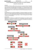
1 2 MAR 12 Introduction Airport -1 q$i Airport Chart Legend . NOTE: This section of the Jeppesen Legend provides a general overview regarding the depiction of Airport diagrams and associated information. The following briefly explains the symbology used on Airport charts throughout the world. Not all items explained apply to all charts. The Airport Chart is divided into specific areas of information as illustrated below. To enhance the usability for larger airports, the Communications and Airport Planview sections are depicted on one side of the Chart . An added Notes Section along with the Additional Runway Information, Take-off minimums, and Alternate minimums sections are depicted on the reverse side of the Chart .
2 FORMAT. 1303320999000. 1303320999000. HEADING. 1303320999000. 1 ICAO indicators and IATA Airport identifiers. 2 Airport elevation. 3 Airport geographic latitude and longitude shown in degrees, minutes, and tenths of minutes. 4 Chart index number. Same as the first approach Chart when the Airport Chart is printed on the reverse side. 5 Chart revision date. 6 Chart effective date. 7 Airport name. 8 Geographic location name. 9 Jeppesen company logo. 1329509537609. q$z JEPPESEN, 2012. ALL RIGHTS RESERVED. Airport -2 Introduction 2 MAR 12 q$i COMMUNICATIONS. For Communications Information See Approach Chart Legend Page APPROACH-2.
3 1303320999000. Airport PLANVIEW. 1303320999000. 1 The planview is a "To Sca le" graphical depiction of the Airport layout, a latitude/longitude grid in degrees, minutes, and tenths of minutes is depicted along the inside of the neat line. 2 The Airport magnetic variation is graphically and numerically depicted. 3 Airport operational notes are placed within the planview. Notes pertaining to a specific area are placed within the area or tied to it. 4 Runway designators (numbers) are magnetic unless followed by a "T" for true. Runway bearings are included when known.
4 5 Physical length of the runway which does not include stopways, overruns, or adjustments for displaced thresholds. Shown in feet with the meter equivalent included at International Airports. 6 The runway end elevation is depicted when known. 7 When applicable, the physical location of displaced thresholds along the runway are shown. 8 Hold short points along the runway are depicted for Land and Hold Short Operations. 9 "Hot Spot" areas are depicted along with a corresponding label when applicable. A textual description is included within the planview or below the additional runway information band.
5 10 When available, stopways and overruns are depicted with the applicable length. 11 When known, the location of RVR transmissometers are shown with any applicable identifiers. 12 All active taxiways and ramp areas are depicted using a grey area fill color. All taxiway identifiers and ramp names are included when known. 13 All known permanently closed taxiways are shown. 14 One of two depictions is used for closed runways depending on the nature of the closure: a. Lengths and designators (numbers) are retained when the closure is temporary. b. Lengths and designators (numbers) are removed when the closure is permanent.
6 15 The configuration and length of all known approach light systems are shown. 1329509537609. q$z JEPPESEN, 2012. ALL RIGHTS RESERVED. 2 MAR 12 Introduction Airport -3 q$i 16 All seaplane operating areas/water runways a re shown. Runway numbers are followed by a "W", the physical length is included along with elevations. 17 The geographical location of the Airport Reference Point (ARP) is depicted when known. 18 Areas under construction are outlined using a light dashed line. 19 When known, the location of the Airport identification beacon is shown. 20 Buildings on or near the Airport are depicted.
7 21 Roads on or near the Airport are depicted. 22 Location of Engineered Materials Arresting System (EMAS) pads are shown and labeled. 23 All known wind direction indicators are depicted. 24 Helicopter landing pads/areas. 25 The geographical location of on Airport VORs and NDBs is indicated and labeled. 26 Pole lines that are on or near the Airport are depicted. 27 All known terrain high points and man-made structures with an elevation 50 feet above the nearest rwy end elevation are depicted. The applicable symbol and elevation are shown. 28 Special use airspace, area outline and designator are depicted.
8 A note, "Entire Chart Lies Within R-XXXX", is shown when the entire Chart planview falls within a particular area. 29 A scale for both feet and meters that is equivalent to the Chart scale is shown. 30 Hazard beacons within the planview are depicted along with an elevation if known. 31 Railroad tracks on or near the Airport are shown. 32 Ditches in the vicinity of the Airport are depicted. 33 Tree lines are depicted. An open ended tree line indicates the border of a forested area. 34 Bluffs are shown with the arrows of the symbol pointing down, or toward lower elevation.
9 1303320999000. ADDITIONAL RUNWAY INFORMATION BAND. 1303320999000. NOTE: For an explanation of the abbreviations used within the Additional Runway Information Band, see the Abbreviations Section. All distances depicted in the Additional Runway Information Band are in feet, the meter equivalent is also shown at International airports. 1 Runway designators/numbers are depicted in the upper left and lower right corners of the box. All information shown to the right within the band applies to the indicated runways. When the information differs between runways, the band is separated with a line.
10 2 All operational runway lighting and approach light systems are listed. 3 Runway surface treatment (grooving) is indicated. 4 "RVR" is depicted when one or more transmissometers are installed along the runway. 5 When different from the physical runway length, landing distance beyond threshold is shown. 6 When applicable, the distance from a point abeam the glide slope transmitter to the roll-out end of the rwy is shown. For PAR, the distance is from the GS interception with the runway. 7 At airports with Land And Hold Short Operations (LAHSO), the distance from the runway threshold to the designated hold short point is shown.