Transcription of AXIAL PISTON PUMPS PV - 3COM-GTN
1 4 AXIAL PISTON PUMPS PVS E R I E S 2 0 C LO S E D C I R C U I T GENERAL DESCRIPTIONA xial PISTON variable displacement PUMPS , Series 20, are of swash plate construction with variable flow capatibility suitable for hydrostatic transmissions with closed circuit. The flow rate is proportional to the pump s driven speed displacement, which, in turn, is determined by the swash plate angle. The latter is infinitely adjustable between zero and maximum displacement. Flow direction is reserved by titting the swash plate to the opposite side of the neutral or zero displacement 1:Figure 2:Figure 2 shows schematically the function of hydrostatic transmission using an AXIAL PISTON variable diplacement pump and fixed displacement PISTON variable displacement PUMPS , Series 20, are well - engineered and easy handle. The full - lenght shaft with a highly efficient tapered roller bearing arrangement offers a high loading capacity for external radial forces.
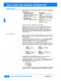
2 Additional PUMPS can be built on. The hydro - mechanical servo displacement control maintains the selected swash plate position and hence pump dis-placement. Upon release of the control handle, the swash plate automatically returns to the null positions and the flow becomes zero. High case pressures can be achieved without leakage even a t the lowest temperatures by using suitable shaft seals. The servo valve arrangement offers the facility to incorporate function regulators and remote control systems. AXIAL PISTON units are designed for easy servicing, complete dismanting and disassembly can be carried out with standard hand tools, and all compo-nents or sub assemblies are PISTON PUMPS PVS E R I E S 2 0 C LO S E D C I R C U I T Figure 3. External drain fluid loss for frame sizes 20 23 Determination of nominal pump sizeTECHNICAL DATAT able 1:+ for higher speeds contact our Application departmentFigure 3.
3 External drain fluid lossfor frame sizes 20 23 Determination of nominal pump size Vg . n . vQe= - ( l/min ) 1000 15,9 . Vg . p Me = - ( Nm ) 100 . mh Mg . n Qe . p Pe = - = 9550 600 tVg displacement ( cm3 ) per revolution p difference high and low pressure( MPa ) n speed ( min 1 ) v volumetric efficiency mh mechanical hydraulic efficiency t total efficiencyPage No. 4 Frame sizeDimension20 21 22 23 24 25 26 27 Max. displacement perrevolution of the variabledisplacement pumpcm333,3 51,6 69,8 89,012,3 12,3 18,8 32,8 32,8 65,518,03 18,03118,7 165,8 227,3 333,7119,54 159,96 196,14 230,51 278,94 348,18 429,59 557,283590 3100 2810 2590 2350 2100 1890 167045 55 63 78124 164 212 270 Max.
4 Flowdm3min-1 Displacement per revolution ofthe charge pumpcm3 Max. pressureMPa35 Nominal pressureMPa21 Max. pressure of controlMPa3,5 Charge pressureMPa0,8 2,0 Max. pressure in caseMPa0,25 continuous 0,5 intermittentMaximum speed + min-1 Minimum speedmin-1500 Nominal speedmin-11500 Kinematic viscosity rangeof working fluid-starting-operating-optimummm2s-110 0012-60025-35 Kind of working fluidmineral oil Operating temperature C -40 to + 50 Max. temperature of workingfluid in tank C 80 Purity of working fluid m10 Direction of shaft rotationclockwise or counter clockwiseMaximum swash plate angle 18 WeightkgTechnical dataTable 1: AXIAL PISTON PUMPS SERIES 20 CLOSED CIRCUIT6 AXIAL PISTON PUMPS PVS E R I E S 2 0 C LO S E D C I R C U I T EXAMPLES OF CURVES DEPENDENCES OF EFFICIENCY, FLOW AND OUTPUT ON THE SPEED(for operating condition of 18 swash plate angle)For frame size PV-20 For frame size PV-22 For frame size PV-23 v - volumetric efficiency t - total efficiency7 AXIAL PISTON PUMPS PVS E R I E S 2 0 C LO S E D C I R C U I T SERVO DISPLACEMENT CONTROL (LINEAR RESPONSE)Regulated by the control handle on the servo valve the swash plate can be infinitely varied in both derections with the help of the servo system.
5 The pump displacement resulting from any control handle position can be esteblished using figures (5a - 5c). The angle of the control handle for stroke initation and for the final position of the stroke can vary from unit to unit within the range of the tolerance band (Figure 5a - 5c).Frame size PV-20 Frame size PV-22 Frame size PV-238 AXIAL PISTON PUMPS PVS E R I E S 2 0 C LO S E D C I R C U I T REVERSING TIME Time for the directional change of the flow from Qmax across 0 to Qmax depending on the size of the control orifice fittesd in the supply port to the servo valve (figure 7).The values given assume movement of the control handle directly from one end position to time of handle: < minimum reversing timeOperating pressure: 21 MPaSpeed: 1450 min-1 Viscosity: 35 diagram of servovalve with alternatine oriffice valve counterbored recessed for orifices reversing time in one flow direction can be extended by inserting an orifice in one of the pilot ports PISTON PUMPS PVS E R I E S 2 0 C LO S E D C I R C U I T AXIAL PISTON PUMPS PV SERIES 20 CLOSED CIRCUIT Dimensions Table 3.
6 Dimensions (mm) Frame size A A1 B B1 B2 B3 C D D3 D4 D5 E F +-0,4 G PV-20 190 146 47,6 112,7 100 122 56 162 127 -0,005 84 25,4 56 15 163 PV-21 191 146 48 124 110 131 70 15 172 PV-22 194 194 48 133 113 135 83 15 172 PV-23 194 194 49 150,8 123,8 146 90 15 190,4 PV-24 213 204 70 167 132 153 75 229 152,4 98 133 21,3 213 PV-25 286 254 80 174 142 162 77 317,5 165,1 98 160 21,3 260 PV-26 285 240 81 197 153 174 317,5 165,1 110 180 21,3 287,4 PV-27 300 274 86 212 172 193 350 177,8 114 208 27,7 317,4 Frame size G1 H H1 H2 H3 L L1 L2 S M N R1 S1 PV-20 81,03 340 270 284 352 224 161,2 93,7 19 -0,25 94,7 55,6 68 100 PV-21 86 358 282 301 367 246 174 106 108,7 65 68 107 PV-22 86 381 311 314 381 256 188 119 112,7 68,3 68,3 111 PV-23 95,2 395 320 327 395 270 194 127 127,6 77,8 68,3 117 PV-24 106.
7 5 498 377 412 510 318 239 169 146 87,3 76 148 PV-25 130 560 423 457 560 366 264 196 153,7 97 76 171 PV-26 143,7 584 451 486 614 388 283 215 170,3 108 76 162 PV-27 158,7 656 475 578 656 433 311 244 187,2 127 76 198 Frame size T U V V1 V3 X Y Z W d d1 f PV-20 9,4 +0,2 19 151 113 115,9 159 3 3 3/8-16 UNC-2B 34,5 -0,17 M10-5H 16 PV-21 160 122 128,6 152 6,35 6,35 PV-22 165 123 128,6 146 9,5 9,5 PV-23 171 134 139,8 140 12,7 12,7 37,68 -0,18 17,5 PV-24 21 186 154 152,3 173 14 14 44,03 M14-5H 23,5 PV-25 199 175 165,1 219 16 16 5/8-11 UNC-2B PV-26 201 214 167,4 235 14,3 16,3 PV-27 225 216 190,5 246 17,5 17,5 64,66 M16 25 Frame size e h1 H2 k l l1 m n H - with charge pump 12cm3 (sizes PV-20 - 23) 33cm3 (size PV-25) H3 - with charge pump 18cm3 (sizes PV-20 - 23) 33cm3 (size PV-24) 66cm3 (size PV-25) PV-20 6,73 62 51,16 48 12,5 min20 45 52,4 26,2 PV-21 68 54 PV-22 71,4 60,5 PV-23 77,7 65 PV-24 88,5 68,2 67 12,45 30 PV-25 98 74 15,6 30 79,4 36,5 PV-26 100 79,4 36,7 PV-27 116 95,3 30 Frame size Port A and B P1,2 drain Port R gear pump M1 , M2 , Z2 PV-20 - 24 SAE flange, 3000 psi 4 threads, 3/8-16 UNC-2B, 18 deep 7/8-14 UNF-2B 7/8-14 UNF-2B 7/16 UNF-2B SAE straight thread O -ring boss PV-25 SAE flange, size 1 1/2 4 threads, 6000 psi, 5/8-11 UNC-2B 35 deep 1 5/16 - 12 UN-2B 1 5/16 - 12 UN-2B PV-26 1 7/8-12 UNF-2B SAE straight threads O ring boss 1 5/16 - 12 UN-2B PV-27 SAE flange, size 1 1/4 3000 psi, 4 threads 7/16-14 UNC-2B Page DIMENSIONST able 3.
8 Dimensions (mm)10 AXIAL PISTON PUMPS PVS E R I E S 2 0 C LO S E D C I R C U I T FIGURE 8 OUTLINE DRAWING FOR AXIAL PISTON VARIABLE DISPACEMENT PUMP, SERIES 20 Deviating control lever of servo - vave in direction:A: Causes high pressure in A orifice in clockwise pump Causes high pressure in B orifice in counter clockwise pumpB: Causes high pressure in B orifice in clockwise pump Causes high pressure in A orifice in counter clockwise pump11 AXIAL PISTON PUMPS PVS E R I E S 2 0 C LO S E D C I R C U I T FIGURE 9: HOSE FLANGEF rame sizeABCD-0,1E-0,1 FHJPV-20 - 2481703552,426,23/8-16 UNC-2 AWasher 10,222,5PV-25 - 27112954679,436,55/8-11 UNC-2 AWasher 1630 Dimensions (mm)Frame sizeABCD-0,1E-0,1 FHJPV-20 - 2481704052,426,23/8-16 UNC-2 AWasher 1022,5PV-25 - 27112956579,436,55/8-11 UNC-2 AWasher 1630 Frame sizeKLM - 0,1N - 0,1OP + 0,2 UPV-20 - 24283882,839,7 0,054V5 - 104PV-25 - 27385012,62,853,9 0,014V6 - 158 Note:Flange according to SAE J 518 cFrame size 20 - 24: size 1, 5000 psi, torque for screw tightening 3/8 - 16 UNC2A: 37 - 42 NmFrame size 25 - 27: size 1 1/2, 6000 psi, torque for screw tightening 5/8 - 11 UNC2A: 158 - 181 NmFIGURE 10: FLANGE FOR PIPING12 AXIAL PISTON PUMPS PVS E R I E S 2 0 C LO S E D C I R C U I T - standard design- available Page No.
9 11 Reversible33,351,669,889,0118,7165,8227, 3333,7 StandartRAotherBCDF21,80 Type designationNNAABACA2021222324252627F4064 ,6618,85 cm365,5 cm3 AXIAL PISTON PUMPS SERIES 20 CLOSED CIRCUITTYPE DESIGNATION13 AXIAL PISTON PUMPS PVS E R I E S 2 0 C LO S E D C I R C U I T TYPES OF CONTROLST ypes of controlsPage No. 12 AXIAL PISTON PUMPS SERIES 20 CLOSED CIRCUIT14 AXIAL PISTON PUMPS PVS E R I E S 2 0 C LO S E D C I R C U I T SPARE PARTS FOR VARIABLE PISTON PUMPPV 20, PV 21, PV 22, PV 23, PV 24, PV 25, PV 26, PV 27At your inquiry is needed to give number of spare parts from sketch and size of the Parts for Variable PISTON PumpPV 20, PV 21, PV 22, PV 23, PV 24, PV 25, PV 26, PV 27At your inquiry is needed to give number of spare parts from sketch and size of the Servovalve Assembly2 Charge Pump Assembly3 Servo Cylinder4 Servo Piston5 Front Cover6 Pump Housing7 End Cap8 Swash Plate9 Check Valve10 Cylinder Barrel11 PISTON Assembly12 Bearing Plate13 Retainer Guide14 Slipper Retainer15 Spring Retainer16 Spring Seat17 Spring Guide18 Bearing Plate Pilot19 Pin20 Cylinder Barrel Spring21 RetainerSpring22 Retaining Ring23 Thrust Plate24 Valve Plate 25 Trunnion26 Seal Retainer27 Rotating Seal28 Stationary Seal29 Drive Shaft 30 Servo Link31 Sleeve Retainer32 SpringGuide33 Shim34 Washer35 Orifice36 Spacer37 Control Handle38 Loop39 Cap41 Control Valve Gasket42 Charge Pump Gasket43 Shim Pack44 End Cap Gasket45 Front Cover
10 Gasket47 Seal Spring 48 Servo Spring49 Nut50 Plastic Plug51 Plug52 Expander 0553 Expander 0954 Hex Head Screw55 Hex Head Screw57 Hex Head Screw58 End Cap Screw59 End Cap Screw60 Screw61 Hex Head Screw62 Pin63 Pin64 Drive Screw65 Pin66 Pin67 Retaining Ring68 Retaining Ring69 Retaining Ring70 O-Ring71 O-Ring72 O-Ring73 O-Ring74 O-Ring75 O-Ring76 O-Ring77 Front Bearing78 Rear Bearing79 Trunnion Bearing80 Washer81 Washer82 Washer83 Drive Screw84 Washer86 Socket Head Screw87 O-Ring89 Hex Head Screw15 AXIAL PISTON PUMPS PVS E R I E S 2 0 C LO S E D C I R C U I T 16 AXIAL PISTON PUMPS PVS E R I E S 2 0 C LO S E D C I R C U I T SPARE PARTS FOR SERVOVALVE ASSEMBLY FOR VARIABLE PISTON PUMPPV 20, PV 21, PV 22, PV 23, PV 24, PV 25, PV 26, PV 27At your inquiry is needed to give number of spare parts from sketch of servovalve assembly and size of the Parts for Servovalve Assembly for Variable PISTON PumpPV 20, PV 21, PV 22, PV 23, PV 24, PV 25, PV 26, PV 27At your inquiry is needed to give number of spare parts from sketch of servovalve assembly and size of the Control Valve Housing 2 Lever Arm 3 Cover 4 Shaft 5 Bushing 6 Spring Bushing 7 Shaft Link 8 Shuttle Valve 9 Set Screw 10 Retaining Nut 11 Retaining Nut 12 Link 13 Valve Link 14 Bushing 15 Bushing16 Stop 17 Washer 18 Torsion Spring 19 Spring 20 Plug 21 Retaining Ring 22 Retaining Ring 23 O-Ring 24 O-Ring 25 O-Ring 26 O-Ring 27 Pin 28 Retaining Ring 29 O-Ring Spare Parts for Charge Pump for Variable PISTON PumpPV 20, PV 21, PV 22, PV 23, PV 24.