Transcription of axial piston variable displacement pump a10vg - …
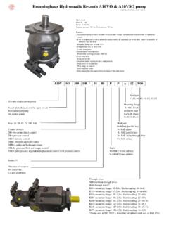
1 IndustrialHydraulicsElectric Drivesand ControlsLinear Motion andAssembly TechnologiesPneumaticsServiceAutomationM obileHydraulicsAxial PistonVariable displacement Pump A10 VGClosed CircuitSizes 1 Nominal pressure 300 barPeak pressure 350 barFeatures variable displacement axial piston pump with swashplate design for hydrostatic closed circuit transmissions Flow is proportional to drive speed and displacement and is infi nitely variable Output fl ow increases with the swivel angle of the swashpla-te from 0 to its maximum value Flow direction changes smoothly when the swashplate is moved through the neutral position A wide range of highly adaptable control instruments is avai-lable for different control and regulating functions The pump is equipped with two pressure relief valves on the high pressure ports to protect the hydrostatic transmission (pump and motor) from overload The pressure relief valves also function as boost inlet valves An integral auxiliary pump serves as boost and pilot oil pump The maximum boost pressure is limited by a built-in boost pressure relief valveRE 92 750 1/36replaces.
2 Code/Standard Program Data - Hydraulic Control, Pilot Pressure Related 8HW - Hydraulic Control, Mechanical Servo 9DA - Hydraulic Control, Speed Related - Hydraulic Control, Direct Operated 12EZ - Electrical Two-Position Control, With Switching Solenoid 12EP - Electrical Control, With Proportional Solenoid 13MD - Mechanical Pivot Control (size 18 only) 14 Unit Dimensions, Size 18 Dimensions, Size 28 Dimensions, Size 45 Dimensions, Size 63 Drive Dimensions of Attachments on a10vg 28 Combination pumps a10vg + a10vg 28 High Pressure Relief Valves 29 Pressure Cut-Off, D 29 Mechanical Stroke Limiter.
3 M 30 Rotary Inch Valve 31 Filtration Types 32 Connector Options for Solenoids 33 Installation Situation for Coupling Assembly 34 Installation and Commissioning Notes 35 Safety Instructions 36 Ordering Code / Standard ProgramAxial piston unitVariable swashplate design, nominal pressure 300 bar, peak pressure 350 barA10 VOperationPump in closed circuitGSize displacement Vg max in cm318 28 45 63 Control device18 28 45 63 Hydraulic control, pilot pressure related HD1 Hydraulic control, mechanical servo HWHydraulic control, speed related DAHydraulic control, direct operated DGElectrical two-position control, with switching solenoid EZElectrical control, with proportional solenoid EPMechanical pivot control MDSolenoid voltage (only for EP, EZ or DA)U = 12 V 1U = 24 V 2 Pressure cut-offwithout pressure cut-off (no code) with pressure cut-off (standard for version with DA control valve) DNeutral position switch (only for HW)without neutral position switch (no code) with neutral position switch LMechanical stroke limiterwithout mechanical stroke limiter (no code) with mechanical stroke limiter, external adjustable MSpring neutral position centering (only MD)without spring neutral position centering (no code) with spring neutral position centering NDA control valveEZ DG EP HW HD D A28 45 63without DA control valve 1with DA control valve, fi xed setting 2with DA control valve, mech.
4 Adjust. with control leverL 3LR 3 Rwith DA control valve, fi xed setting and connections for master controller 7with DA control valve, fi xed setting, andhydraulic inch valve built-on, controlwith brake fl uid 4with mineral oil 8with DA control valve, mech. adjust. with control lever and hydraulic inch valve built-on, control with brake fl uidL 5LR 5 Rwith DA control valve, mech. adjust. with control lever andhydraulic inch valve built-on, control with mineral oilL 9LR 9 RDA control valve with control leverwithout control lever (no code) with control lever - anti-clockwise operation directionLwith control lever - clockwise operation directionRSeriesSeries 1, Index 0102/36 Bosch Rexroth AG | Mobile Hydraulics a10vg | RE 92 750 of rotation18 28 45 63viewed on shaft end clockwise Ranti-clockwise LSeals18 28 45 63 NBR, shaft seal in FKM (fl uor-caoutchouc) NShaft end (permissible input torque see page 7)18 28 45 63splined shaftANSI standard for single pump Sstandard for combination pump TMounting fl angeSAE J744 2-holeCService line ports18 28 45 63 SAE fl ange ports A and B, (metric fastening thread) at side (same side) 10threaded ports A and B (metric)
5 , st side (same side) 16 Auxiliary pump and through driveAuxiliary pumpFlange SAE J744 1)Splined shaft hub 2)without N00with F00with82-2 (A)5/8 in 9T 16/32 DP F01101-2 (B)7/8 in 13T 16/32 DP F021 in15T 16/32 DP F04127-2 (C)1 1/4 in 14T 12/24 DP F07without82-2 (A)5/8 in 9T 16/32 DP K01101-2 (B)7/8 in 13T 16/32 DP K021 in15T 16/32 DP K04127-2 (C)1 1/4 in 14T 12/24 DP K07 Valvessetting rangewith high pressure relief valve,direct controlled, (fi xed setting) barwithout bypass 3with bypass barwithout bypass 4with bypass 6 FiltrationFiltration in the suction line of the auxiliary (boost) pump SFiltration in the pressure line of the auxiliary (boost) pump,ports for external boost circuit fi lter, (Fe and G (Fa)) DExternal supply (model without integral auxiliary pump - N00, ) ERange of male connectors for solenoids (only for EP, EZ and DA)DEUTSCH male connector injection molded, 2-pin (without quenching diode) PDEUTSCH male connector injection molded, 2-pin (with bi-directional quenching diode) 3) QDIN male connector to Hirschmann (without quenching diode) (not for new projects) H1) 2 2-hole2) splined shaft hub to ANSI (splined shaft allocation to SAE J744, see pages 26-27)3) only for control EZ and DA4) no code = standard version, S = special version, K = combination with mounted part or mounted pump = available = available on request = not available = preferred programAxial piston unitOperationSizeControl deviceSeries, IndexA10VG G / 10 N C 4)
6 RE 92 750 | a10vg Mobile Hydraulics | Bosch Rexroth AG 3/364/36 Bosch Rexroth AG | Mobile Hydraulics a10vg | RE 92 750 DataFluidBefore starting a project, get detailed information about the selection of pressure fl uids and application conditions from our catalog sheets RE 90220 (mineral oil), RE 90221 (envi-ronmentally acceptable hydraulic fl uids) and RE 90223 (fi re resistant hydraulic fl uids, HF).The variable displacement pump a10vg is unsuitable for operation with HFA, HFB and HFC. For operation with HFD or environmentally acceptable hydraulic fl uids, restrictions in the technical data and seal selection must be noted; inquire if necessary (please state the hydraulic fl uid to be used in plain text in the order).
7 Operating viscosity rangeFor optimum effi ciency and service life, select an operating viscosity (at operating temperature) within the optimum range of opt = opt. operating viscosity mm2/sdepending on the circuit temperature (closed circuit).Limits of viscosity rangeThe limiting values for viscosity are as follows: min = 5 mm2/sshort term (t < 3 min)at max. perm. temperature of tmax = +115 that the max. hydraulic fl uid temperature of 115 C may not be exceeded even locally ( in the bearing area). max = 1600 mm2/sshort term (t < 3 min)at cold start (p 30 bar, n 1000 rpm, tmin = -40 C). Only for starting up without load. Optimum operating viscosity must be reached within approx. 15 measures are necessary in the temperature range from -40 C to -25 C, please contact detailed information about use at low temperatures, see RE diagramtmin = -40 Ctmax = +115 C5104060201002004006001000160025000 20 40 60 80 100 -40 -20 -25 -10 10 30 50 90 115 70 0 VG 22VG 32VG 46VG 68VG 100 Notes on the selection of the hydraulic fl uidTo choose the correct hydraulic fl uid, it is necessary to know the operating temperature in the circuit (closed circuit), depending on the ambient hydraulic fl uid should be selected so that the operating viscosity is in the optimum range ( opt) in the operating temperature range, see selection diagram, shaded area.
8 We recommend choosing the higher viscosity : At an ambient temperature of X C an operating temperature of 60 C is set in the circuit. In the optimum operating viscosity range ( opt; shaded area) this corresponds to the viscosity classes VG 46 or VG 68; choose: VG : The leakage oil (case drain oil) temperature is infl u-enced by pressure and pump speed and is always higher than the circuit temperature. However, the temperature must not exceed 115 C at any point in the the above conditions cannot be satisfi ed in the case of extreme operating parameters or high ambient temperatures, please contact fl uid temperature rangeTemperature t in CViscosity in mm2/sRE 92 750 | a10vg Mobile Hydraulics | Bosch Rexroth AG 5/3610001234562000 3000 4000 5000 Technical DataFiltrationThe fi ner the fi ltration, the higher the cleanliness class of the hydraulic fl uid and the longer the life of the axial piston unit.
9 To ensure functional reliability of the axial piston unit at least cleanliness class 20/18/15 to ISO 4406 is on the system and the application, for the a10vg we recommendfi lter elements 20 100 With a rising pressure differential at the fi lter element, the -value must not very high hydraulic fl uid temperatures (90 C to max. 115 C) at least cleanliness class 19/17/14 to ISO 4406 is the above classes cannot be observed, please contact us. For notes on fi ltration types, see page seal temperature rangeThe FKM shaft seal ring is permissible for housing temperatures of -25 C to +115 :For applications below -25 C, an NBR shaft seal is necessary (permissible temperature range: -40 C to +90 C). Please state NBR shaft seal in plain text when orderingOperating pressure rangeInletVariable displacement pump (with external supply, E):For control devices EP, EZ, HW and HD1 Boost pressure (at n = 2000 rpm) pSp_____18 barFor control devices DA, DGBoost pressure (at n = 2000 rpm) pSp_____ 25 barAuxiliary pump:Suction pressure ps min ( 30 mm2/s) ____ bar ab so luteFor cold start _____ bar absoluteOutletVariable displacement pump: Pressure at port A or BNominal pressure pN_____ 300 barPeak pressure pmax_____ 350 barSummation pressure (pressure A + pressure B) pmax_ 600 barAuxiliary pump:Peak pressure pH max size 18 _____ 25 barSummation pressure pH max size 28, 45, 63 _____ 40 bar(pressure data according to DIN 24312)perm.
10 Pressure pabs. max. in barspeed n in rpmSize 18 Size 28 Case drain pressureThe lower the speed and the case drain pressure, the longer the service life of the shaft seal ring. The values shown in the diagram are permitted maximum values for a shaft seal ring under intermittent pressure and must not be exceeded. Stationary pressure loads within the range of the maximum permitted leakage pressure may reduce the service life of the shaft seal loads of up to 6 bar are acceptable for short periods (t < 5 min), regardless of 63 Size 456/36 Bosch Rexroth AG | Mobile Hydraulics a10vg | RE 92 750 the nominal valueVg n vFlowqv=l/min 1000Vg pTorqueT = Nm20 mh2 T nqv p PowerP ==kW60 000600 tTechnical DataTable of values (theoretical values, without effi ciencies and tolerances; values rounded)Size18284563 displacement variable displacement pump Vg maxcm318284663 Auxiliary pump (at p = 20 bar) Vg at Vg maxnmax continuousrpm4000390033003000 Limited maximum 1)nmax limitedrpm4850420035503250 Intermittent maximum 2)nmax interm.