Transcription of Axial Piston Variable Pump RE 92500/10.09 1 A11VO
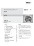
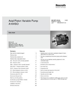
1 Linear Motion andAssembly TechnologiesServicePneumaticsHydraulicsE lectric Drives and ControlsAxial Piston Variable PumpA11 VOData sheetSeries 1 Size NG40 to 260 Nominal pressure 350 barMaximum pressure 400 barOpen circuitFeaturesVariable Axial Piston pump of swashplate design for hydrosta- tic drives in open circuit hydraulic primarily for use in mobile applications. The pump operates under self-priming conditions, with tank pressurization, or with an optional built-in charge pump (impeller).A comprehensive range of control options is available matching any application control option is externally adjustable, even when the pump is through drive is suitable for adding gear pumps and Axial Piston pumps up to the same, 100% through output flow is proportional to the drive speed and infinitely Variable between qV max and qV min = 92500 1/64 Replaces.
2 ContentsOrdering Code / Standard Program 2 Technical Data 5LR Power Control 9DR Pressure Control 20HD Hydraulic Control, Pilot-Pressure Related 24EP Electric Control with Proportional Solenoid 26 Dimensions, Size 40 28 Dimensions, Size 60 32 Dimensions, Size 75 36 Dimensions, Size 95 40 Dimensions, Size 130/145 44 Dimensions, Size 190 48 Dimensions, Size 260 52 Through Drive Dimensions 56 Overview of Attachments for A11V(L)O 58 Combination pumps A11VO + A11VO 58 Swivel Angle Indicator 59 Connector for Solenoids 60 Installation Notes 61 General Notes 642/64 Bosch Rexroth AGA11VO Series 1 RE 92500 Code / Standard ProgramAxial Piston unit01 Swashplate design, Variable , nominal pressure 350 bar, maximum pressure 400 barA11 VCharge pump (impeller)40 60 75 95 130 145 190 26002without charge pump (no code) with charge pump LOperation03 Pump, open circuitOSize04 Displacement Vg max in cm340 60 75 95 130 145 190 260 Control unit05 Power controlLR LRwith overridecross sensingnegativeLRC LR.
3 Chigh-pressure relatednegativeLR3 LR3pilot-pressure relatednegativeLG1 LG1positiveLG2 LG2electricU = 12 VnegativeLE1 LE1U = 24 VnegativeLE2 LE2with pressure cut-offD L . D..hydraulic, 2-stageE L . E..hydraulic, remote controlledG L .. load sensingS L ..Selectric, prop. override, 24 VS2 L ..S2hydraulic, prop. overrideS5 L ..S5with stroke limiternegative characteristic p = 25 barH1 L ..H1 p = 10 barH5 L ..H5positive characteristic p = 25 barH2 L ..H2 p = 10 barH6 L ..H6U = 12 VU1 L ..U1U = 24 VU2 L ..U2 Pressure controlDR DRwith load sensingDRS DRSremote controlledDRG DRGfor parallel operationDRL DRLH ydraulic control, p = 10 barHD1 HD1pilot-pressure related(positive characteristic) p = 25 barHD2 HD2with pressure cut-offD pressure cut-off, remote controlledG HD.
4 GElectric controlU = 12 VEP1 EP1with proportional solenoid(positive characteristic)U = 24 VEP2 EP2with pressure cut-offD EP. Dwith pressure cut-off, remote controlG EP. GA11VO/1 N01020304050 6070 80 910111213141516In case of controls with several additional functions, observe the order of the columns, only one option per column is possible ( LRDCH2). The following combinations are not available for the power control: LRDS2, LRDS5, , , , and the combination in conjunction with the stroke limiters H1, H2, H5, H6, U1 and 92500 A11VO Series 1 Bosch Rexroth AG 3/64 Ordering Code / Standard ProgramSeries061 Index07 Size 40 .. 1300 Size 145 .. 2601 Direction of rotation08 Viewed from shaft endclockwiseRcounter-clockwiseLSeals09 NBR (nitrile-caoutchouc), shaft seal ring in FKM (fluor-caoutchouc)NShaft end (see page 8 for permissible input and through drive torques)40 60 75 95 130 145 190 26010 Splined shaft DIN 5480 for single and combination pump ZParallel keyed shaft DIN 6885 PSplined shaft ANSI 1976for single pump Sfor combination pump 1) 1) 1) TMounting flange40 60 75 95 130 145 190 26011 SAE J744 2-hole CSAE J744 4-hole DSAE J617 2) (SAE 3) GService line ports40 60 75 95 130 145 190 26012 Pressure and suction port SAE, at side, opposite side(with metric fastening threads)
5 12 Through drive (see page 58 for attachments)40 60 75 95 130 145 190 26013 Flange SAE J744 3)Coupler for splined shaft N0082-2(A)5/8in9T 16/32DP(A) K013/4in11T 16/32DP(A-B) K52101-2(B)7/8in13T 16/32DP(B) K021 in15T 16/32DP(B-B) K04W352x30x16x9g K79127-2(C) 4)1 1/4in14T 12/24DP(C) K071 1/2in17T 12/24DP(C-C) K24W302x30x14x9g K80W352x30x16x9g K61152-4(D)1 1/4in14T 12/24DP(C) K861 3/4in13T 8/16DP(D) K17W402x30x18x9g K81W452x30x21x9g K82W502x30x24x9g K83165-4(E)1 3/4in13T 8/16DP(D) K72W502x30x24x9g K84W602x30x28x9g K67A11VO/1 N010203040506070809101112131415164/64 Bosch Rexroth AGA11VO Series 1 RE 92500 angle indicator (page 59)40 60 75 95 130 145 190 26014without swivel angle indicator (no symbol) with optical swivel angle indicator Vwith electric swivel angle sensor RConnector for solenoids (page 60)40 60 75 95 130 145 190 26015 DEUTSCH connector molded, 2-pin without suppressor diode PStandard / special version16 Standard versionwithout symbolcombined with attachment part or attachment pump-KSpecial version-Scombined with attachment part or attachment pump-SK1) S-shaft suitable for combination pump!
6 2) To fit the flywheel case of the combustion engine3) 2 2-hole; 4 4-hole4) Size 190 and 260 with 2 + 4-hole flange = available = on request = not available = preferred programA11VO/1 N01020304050607080910111213141516 Ordering Code / Standard ProgramRE 92500 A11VO Series 1 Bosch Rexroth AG 5/64 Technical DataHydraulic fluidBefore starting project planning, please refer to our data sheets RE 90220 (mineral oil), RE 90221 (environmentally acceptable hydraulic fluids) and RE 90223 (HF hydraulic fluids) for detailed information regarding the choi-ce of hydraulic fluid and operating Variable pump A11VO is not suitable for operating with HFA, HFB and HFC. If HFD or environmentally acceptab-le hydraulic fluids are being used, the limitations regarding technical data and seals mentioned in RE 90221 and RE 90223 must be ordering, please indicate the used hydraulic viscosity rangeFor optimum efficiency and service life, select an operating vis-cosity (at operating temperature) within the optimum range of opt = optimum operating viscosity 16 to 36 mm2/sdepending on the tank temperature (open circuit).
7 Limits of viscosity rangeThe limiting values for viscosity are as follows: min = 5 mm2/s Short-term (t < 3 min) At max. perm. temperature of tmax = +115 C. max = 1600 mm2/s Short-term (t < 3 min) At cold start (p 30 bar, n 1000 rpm, tmin = -40 C). Only for starting up without load. Optimum operating viscosity must be reached within approx. 15 that the maximum hydraulic fluid temperature of 115 C must not be exceeded locally either ( in the bearing area). The temperature in the bearing area is depending on pressu-re and speed up to 5 K higher than the average case drain measures are necessary in the temperature range from -40 C and -25 C (cold start phase) , please contact us. For detailed information about use at low temperatures, see RE diagramtmin = -40 Ctmax = +115 C-40 -25 -10 10 30 50 90 115 70 0 51040602010020040060010001600-40 0 20 40 60 80 100 -20 1600 22VG 32VG 46VG 68VG 1005 Hydraulic fluid temperature rangeTemperature t in CViscosity in mm2/sDetails regarding the choice of hydraulic fluidThe correct choice of hydraulic fluid requires knowledge of the operating temperature in relation to the ambient temperature: in an open circuit the tank hydraulic fluid should be chosen so that the operating vis-cosity in the operating temperature range is within the optimum range ( opt.)
8 See the shaded area of the selection diagram. We recommended that the higher viscosity class be selected in each : At an ambient temperature of X C an operating tem-perature of 60 C is set. In the optimum operating viscosity range ( opt; shaded area) this corresponds to the viscosity classes VG 46 and VG 68; to be selected: VG note: The case drain temperature, which is affected by pressure and speed, is always higher than the tank temperature. At no point in the system may the temperature be higher than 115 the above conditions cannot be maintained due to extreme operating parameters, please contact finer the filtration, the higher the cleanliness level of the hyd-raulic fluid and the longer the service life of the Axial Piston unit.
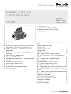
9 To ensure functional reliability of the Axial Piston unit, the hyd-raulic fluid must have a claenliness level of at least 20/18/15 according to ISO very high hydraulic fluid temperatures (90 C to max. 115 C, not permitted for sizes 250 to 1000) at least cleanliness level 19/17/14 according to ISO 4406 is the above classes cannot be observed, please contact Data6/64 Bosch Rexroth AGA11VO Series 1 RE 92500 DataOperating pressure rangeInletAbsolute pressure at port S (suction port)Version without charge pumppabs min _____ barpabs max _____ 30 barIf the pressure is > 5 bar, please with charge pumppabs min _____ barpabs max _____2 barMaximum permissible speed (speed limit)Permissible speed by increasing the inlet pressure pabs at the suction port S or at Vg Vg max1, 20,80,91, 00,91, 01,1pabs = 1 barSpeed nmax /nmax1 Displacement Vg / Vg maxpabs = barOutletPressure at port A or BNominal pressure pN _____ 350 barMaximum pressure pmax _____ 400 barNominal pressure: Max.
10 Design pressure at which fatigue strength is pressure: Max. operating pressure which is permissible for short-term (t < 1s).Minimum operating pressureA minimum operating pressure pB min is required in the pump service line depending on the speed, the swivel angle and the displacement (see diagram).0,501,020181614121086pB (bar)Vg max n (with charge pump)n (without charge pump)Case drain pressureThe case drain pressure at the ports T1 and T2 maybe a maximum of bar higher than the inlet pressure at the port S but not higher thanpL abs. max _____ 2 unrestricted, full size case drain line directly to tank is range of the shaft seal ringThe FKM shaft seal ring is permissible for case drain tempera-tures of -25 C to +115 :For applications below -25 C, an NBR shaft seal ring is neces-sary (permissible temperature range: -40 C to +90 C).