Transcription of B-32:B-32 7/9/09 2:52 PM Page 1 Series DH …
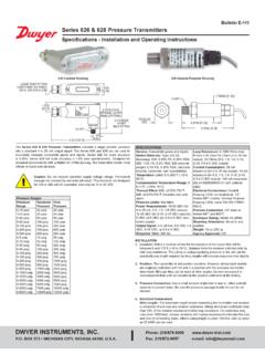
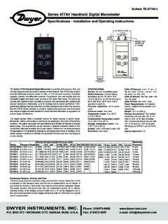
1 Bulletin B-32 Series DH Digihelic differential pressure ControllerSpecifications - Installation and Operating InstructionsDWYER INSTRUMENTS, INC. Phone: 219/879-8000 BOX 373 MICHIGAN CITY, IN 46361, Fax: 219/872-9057 e-mail: 7/9/09 2:52 PM Page 11 DIMENSIONS1-3/4[ ]4-1/2[ ]1/2[ ]4-1/2[ ]3-19/32[ ]1-15/16[ ]3-25/32[ ]Face Designed to Meet NEMA 4X (IP66)PANEL CUT in. + - ( mm + - ) in. + - ( mm + - ) B-32:B-32 7/9/09 2:52 PM Page 22 SPECIFICATIONSS ervice:Air and non-combustible, compatible Materials:Consult Material: ABS plastic, UL approved : at 77 F (25 C) including hysteresis and repeatability (after 1 hourwarm-up).
2 Stability:< 1% per Limits:Ranges in. = 2 psi5 : 5 psi; 10 : 5 psi; 25 : 5 psi; 50 : 5 psi; 100 : 9 Limits:32 to 140 F (0 to 60 C).Compensated Temperature Limits:32 to 140 F (0 to 60 C).Thermal F ( C) from 77 F (25 C).Power Requirements:High Voltage Power = 100 to 240 VAC, 50 to 400 Hz or 132 to 240 Voltage Power = 24 VDC 20%.Power Consumption:Low Voltage Power = 24 VDC - 130 mA Voltage Power = 100 to 240 VAC, 132 to 240 VDC - 7VA Signal: 4-20 mA DC into 900 ohms & Span Adjustments:Accessible via Time:250 ms (dampening set to 1).Display:4 digit LCD height LED indicators for set point and alarm Connections:Screw Connections:Compression fitting for use with 1/8 ID tubing x 1/4 ODtubing ( mm ID x mm OD).
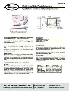
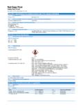
3 Enclosure Rating:Face designed to meet NEMA 4X (IP66).Mounting Orientation:Mount unit in horizontal :1/8 DIN. Panel Cutout: x in (45 x 92 mm). oz (408 g).Serial Communications:Modbus Protocol RTU, RS485, 9600 Approvals:UL Listed, CUL Listed File No. E83725 CE EMC and Low Voltage Directives:EN61000-4-2EN61000-4-3*EN6100 0-4-4EN61000-4-5EN61000-4-6EN61000-4-11E N55011EN601010* Models DH-001 through DH-004, DH-011 through DH-014 pass criteria B. All others pass criteria SPECIFICATIONSS witch Type:2 SPDT Rating:8 Amps at 240 VAC Point Adjustment:Adjustable via keypad on :B-32 7/9/09 2:52 PM Page 33 WIRING2020191918181717161615151414131311 11121210109876543212121222223232424 CCN/CN/CN/CN/CN/ON/ON/ON/OSP1 RELAYSP1 RELAYSP2 ORALARMRELAYSP2 ORALARMRELAY3/8A 250 VACMEDIUM LAG3/8A 250 VACMEDIUM LAG100-240 VAC or132-240 VDC POWER100-240 VAC or132-240 VDC POWERNOTE1 NOTE1AB_+RS485 SERIALCOMMUNICATIONRS485 SERIALCOMMUNICATION_+24 VDC POWER24 VDC POWERREMOTE RESETSWITCHREMOTE RESETSWITCHNOTE 1 NOTE 14-20mAtransmitteroutput4-20mAtransmitte routputDevice receiving 4-20mAsignal.
4 Check specificationsof this device for input loadresistance. Typical 250 to600 OHMS, 900 OHMS maximumsignal. Check specificationsof this device for input loadresistance. T600 OHMS, 900 OHMS maximum__++_+High pressure PortHigh pressure PortLowPressurePortLowPressurePortNOTES: 1. The instrument may be powered from the AC line or 24 VDC. Do not wire ACline terminals 4-5 and 24 VDC terminals 14-15 at the same time or damage tothe unit will For supply connections, wire in accordance with an equivalent national standardor code. Use copper conductors only rated for at least 75 C. 3. Terminals 11-15, 18 and 20 are rated CLASS ISOLATION:Relays - 1500 VAC to all other inputs and Line Power (terminals 4-5) - 1500 VAC to all other inputs and output - 500 VAC to all other CLASS 2 24 VDC Power, 4-20 mA transmitter, and Remote Reset Switch share a common The Remote Reset Switch must be a dry contact Shielded cable is required for RS485 WARNINGIf Digihelic is powered by 24 VDC, the device receiving the 4-20 mA transmitteroutput MUST NOT share a common ground with the 24 VDC supply or damageto the Digihelic will result.
5 B-32:B-32 7/9/09 2:52 PM Page 44It is not necessary to remove the control chassis from the housing forinstallation. If the control chassis is removed from the housing, youmust follow industry standard practice for control and protectionagainst Electro-Static Discharge (ESD). Failure to exercise good ESDpractices may cause damage to the to housing terminals while chassis is removed may cause dis-tortion of the internal connector and possible damage to the connec-tor when the chassis is reinstalled. It is strongly recommended thatthe control housing be wired with the chassis the instrument in a location that will not be subject to excessive temperature,shock or vibration.
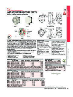
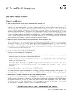
6 All models are designed for mounting in an enclosed the position desired for the instrument on the panel. Prepare the panel by cut-ting and deburring the required the front of the panel, slide the instrument through the cut out. The housinggasket should be against the housing flange before the rear of the panel slide the mounting collar over the housing. Hold the hous-ing with one hand and using the other hand, push the collar evenly against the paneluntil the springs are compressed. The ratchets will hold the mounting collar andhousing in 2020191918181717161615151414131311111212 1010987654321212122222323242420201919181 8171716161515141413131111121210109876543 2121212222232324242020191918181717161615 1514141313111112121010987654321212122222 3232424___+++SHIELDSHIELDSHIELDSHIELDTIE SHIELD TO EARTH GROUNDTIE SHIELD TO EARTH GROUNDTO RS232 TORS485 CONVERTERTO RS232 TORS485 CONVERTER120 OHMRESISTOR120 OHMRESISTORLAST UNIT ON RS485 BUSSLAST UNIT ON RS485 BUSSWIRE NUTWIRE NUT - RS485 WIRING TO DAISY CHAIN INSTRUMENTS ON THE RS485 BUSSUP TO 128 UNITS MAY BE DAISY CHAINEDTHE 120 OHM RESISTORIS USUALLY
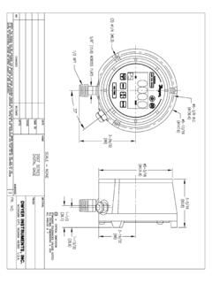
7 ONLYNECESSARY FOR LONGWIRE 120 OHM RESISTORIS USUALLY ONLYNECESSARY FOR LONGWIRE CONTROLER RS485 WIRING B-32:B-32 7/9/09 2:52 PM Page 55SP1SP1SP2SP2 ALHIALHIALLOALLOSP/ALSP/ALRSTRSTMENUMENU EX1KX1 KMULTIPLIER DESCRIPTORMULTIPLIER DESCRIPTORVISIBLE WITH SVISIBLE WITH SOME VELOCITYME VELOCITYAND FLOW RANGEAND FLOW RANGEFRONT PANELFRONT PANELPRESSUREVALUEPRESSUREVALUEUNITSUNIT SALARMALARMDESCRIPTORDESCRIPTORSP2 DESCRIPTORSP2 DESCRIPTORSP1 DESCRIPTORSP1 DESCRIPTORSP/ALSP/ALMENUERSTPAGE 1 OF 128/25/03SP/ALMENUMENUERSTPAGE 1 OF 128/25/03SP/ALMENUERSTPAGE 1 OF 128/25/03SP/ALMENUERSTPAGE 1 OF 128/25/03SP/ALMENUERSTPAGE 1 OF 128/25/03SP/ALMENUERSTRSTPAGE 1 OF 128/25/03 HOME POSITION FUNCTIONS equences the displaythrough SET POINT andALARM settingsAllows access
8 To themenusDisplays full scale range of unitClears or resets an Alarm(alarm set for manualreset)MAIN MENU FUNCTIONR eturn to homepositionReturn to home positionSequences throughmenusSequences throughmenusEnter into SUB MENUSUB MENU FUNCTIONR eturn to home positionReturn to previous menuIncrements a valueDecrements a valueChanges a value or setting. Press ENTERand display will with UP or DOWN arrows. Press ENTER tostore. Display will SUB MENU resets display topresent ARROWDOWNARROWENTERRESETKEY FUNCTIONSB-32:B-32 7/9/09 2:52 PM Page 66 SETTING SET POINTS AND ALARMSThe hot key provides direct access to the Set Point and Alarm MENU.
9 TheSet Point and Alarm MENUS that are displayed are based upon the Control (CtrL)SUB whenVisible whenVisible whenVisible whenVisible whenVisible whenmode =mode =mode =mode =mode =mode =CONTROL MODECONTROL MODECONTROL MODECONTROL MODECONTROL MODECONTROL MODESET POINT ADJUSTMENTA djusting the Digihelic controller Set Points is quick and simple. Instead of settinga set point and deadband, simply adjust SP1 Hor SP2 Hfor the desired relay turnon point, and then adjust SP1 Lor SP2 Lfor the desired relay turn off (in. )In the above graph, an instrument with a range would have the SP1 relay turnon at and off at . SP1 Hsets the relay turn on point, and SP1 Lsets the relayturn off point.
10 The relays outputs normally function in the direct acting mode, whichmeans the relays turn on with an increase in pressure . SP1 may be configured to actas a reverse acting relay (refer to the 1SP SUB MENU setting, page 15). When setfor reverse acting, SP1 Hsets the relay turn OFF point, and SP1 Lsets the relay turnON point. SP2 is always direct :B-32 7/9/09 2:52 PM Page 77 MENU MAPMENU MAPCONTINUEDCONTINUEDSETTINGSSETTINGSMAI N MENUS SUB MENUSMENUSUNAVAILABLEFOR BI-DIRECTIONALRANGES ANDRANGES ABOVE 25 IN. 1 OF 128/25/03SP/ALMENUERSTPAGE 1 OF 128/25/03SP/ALMENUERSTPAGE 1 OF 128/25/03SP/ALMENUMENUERSTPAGE 1 OF 128/25/03B-32:B-32 7/9/09 2:52 PM Page 88 CONTINUEDCONTINUEDSETTINGSSETTINGSMAIN MENUSSUB MENUSSP/ALMENUERSTPAGE 1 OF 128/25/03SP/ALMENUERSTPAGE 1 OF 128/25/03SP/ALMENUERSTPAGE 1 OF 128/25/03SP/ALMENUMENUERSTPAGE 1 OF 128/25/03B-32:B-32 7/9/09 2:52 PM Page 99 PAGE 5 OF 12 MAIN MENUS SUB MENUSSETTINGSM enus present onlyin pressure operationSP/ALMENUERSTPAGE 1 OF 128/25/03SP/ALMENUERSTPAGE 1 OF 128/25/03SP/ALMENUERSTPAGE 1 OF 128/25/03SP/ALMENUMENUERSTPAGE 1 OF 128/25/03B-32:B-32 7/9/09 2.