Transcription of B-33:B-33 7/30/10 9:36 AM Page 1 Series 3000 Photohelic ...
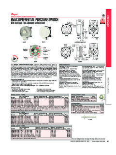
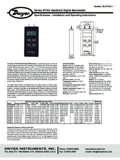
1 The Photohelic Switch/Gageis a very versatile, precise pressureswitch combined with the time-proven Magnehelic pressure are available with one or two phototransistor actuated reading is unaffected by switch operation. Easy to adjust set pointshave knob controls. Applied pressure and switch set points are fullyvisible at all times. Deadband is one pointer width - less than 1% of fullscale. Double-pole double-throw relays can be easily interlocked toprovide variable deadband control. For positive, negative or differentialpressure only on 3600S models. Full scale ranges available from to 0-6000 gage SENSING - HOW IT WORKSIn a typical control application, the Photohelic switch/ gage controlsbetween high and low pressure set points. When pressure changes,reaching either set point pressure , the beam from an LED to the limitingphototransistor will be cut off by the helix-driven light shield.
2 Theresulting signal change is electronically amplified to actuate its DPDT slave relay and switching occurs. Dead band between make and breakis 1% of full scale or less - just enough to assure positive, 3000 Photohelic pressure Switch/ gage Specifications - Installation and Operating Instructions Bulletin B-33 DWYER INSTRUMENTS, INC. Phone: 219/879-8000 BOX 373 MICHIGAN CITY, INDIANA 46361, Fax: 219/872-9057e-mail: SPECIFICATIONSS ervice: Air and non-combustible, compatible Materials: Consult : 2% of full scale at 70 F ( C). 3% on -0 and 4% on-00 models. pressure Limits: -20 Hg. to 25 psig ( to bar). MP option;35 psig ( bar), HP option; 80 psig ( bar). 36003S 36010S;150 psig ( bar). 36020S and higher; x full scale pressure . Temperature Limits: 20 to 120 F ( to C); Low temperatureoption available. Process Connections: 1/8 female NPT. Size: 4 ( mm) dial face, 5 (127 mm) x 8-1/4 ( mm).
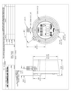
3 Weight: 4 lb ( kg). SWITCH SPECIFICATIONSS witch Type: Each setpoint has 2 Form C relays (DPDT).Repeatability: 1% of full Rating: 10A @ 28 VDC, 10A @ 120, 240 Connections: Screw Requirements: 120 VAC, 50/60 Hz; 240 VAC Power Orientation: Diaphragm in vertical position. Consult factoryfor other position Point Adjustment: Adjustable knobs on face. 2-1/2 [ ]2-1/16 [ ]2 [ ]1-1/4[ ](4) 6-32 HOLESEQUALLY SPACED ONA 5-1/8 [ ] 4-47/64[ ] 5[ ] 4 [ ]FACE5-1/2 [ ] RING5/8 [ ]5/8 [ ] PANEL MAX3/16 [ ]3-7/8 [ ]5-1/8 [ ]6-3/8 [ ](7-5/8 [ ])4-3/8 [ ]HOUSING REMOVAL3/4 CONDUITCONNECTION 4-3/4[ ]3-7/8 SQ[ ]1/8 FEMALE NPT HIGH pressure CONNECTION1/8 FEMALE NPT LOWPRESSURE CONNECTIONFig. 1B-33:B-33 7/30/10 9:36 AM Page 1 INSTALLATION1. LocationAll parts of the Dwyer Photohelic pressure switch/ gage are ruggedlyconstructed and will stand a moderate amount of vibration, physicalshock, and handling. Normal care in handling and installation is all thatis required.
4 In cases where instrument panel vibration is severe, thepanel should be a spring mounted or the amplifier-relay unit mountedremotely on a more stable a location where the ambient temperature will not exceed 120 pressure sensing lines may be run any necessary example, 250 foot sensing lines will not affect accuracy but will dampthe reading slightly. Do not restrict lines. If pulsating pressure or vibrationcauses excessive pointer oscillation or relay chatter, consult factory foradditional damping means. 2. PositionThe Photohelic pressure Switch/ gage may be mounted as an integralpackage or the amplifier-load relay assembly and housing may bemounted remotely from the indicating gage -phototransistor cords with 7 pin plugs and receptacles are available fromDwyer for interconnection of the two unit may be mounted in any desired position, scale vertical orhorizontal, without affecting its accuracy, but must be rezeroed if positionis changed from horizontal to vertical or vice versa.
5 The -0 and -00models must be mounted with the scale MountingThe Photohelic Switch/ gage is normally mounted before makingelectrical connections, as the electrical enclosure is independent of themounting means and may be removed at any MountingNormal mounting is flush or through panel is shown in Fig. 2. Be sure toallow 4-3/8 extra space behind the unit for electrical enclosure a single 4-13/16 diameter hole in the panel. Insert the entirePhotohelic Switch/ gage unit from the front, then slip on the mountingring and snap ring from the rear. Seat the snap ring in its groove, backup the mounting ring against snap ring and tighten the four (4) 2 No. 6-32 clamp screws provided. If behind panel space is critical, the amplifier-relay unit can be mounted remotely. See the Remote-Relay MountingInstructions for B-33 page 2 Fig. 2 SNAP RING GROOVE4-13/16 (122 mm) DIA. HOLE REQUIRED FOR PANEL MOUNTING1/8 MALE NPT pressure CONNECTIONS.
6 SINGLE HIGH pressure CONNECTION FOR Series 36000A Panel MountingB-33:B-33 7/30/10 9:36 AM Page 2 gage Mounting with Relays RemoteWhere it is desirable to mount the amplifier-relay unit separate from thegage-phototransistor unit, the gage may be mounted either as shown inFig. 2 (except less amplifier-relay portion) or surface mounted as shownin Fig. 3A. Use the layout shown in Fig. 3B to locate holes. The completepackage cannot be surface Relays MountingThe amplifier - relay unit may be mounted remotely as shown in Fig. the hole layout as shown in Fig. 4B for this mounting information for special requirements is availablefrom the Pneumatic Connections & ZeroingAfter installation but before making pressure connections, set theindicating pointer exactly on the zero mark, using the zero adjust screwlocated at the bottom of the front cover. Note that this adjustment canonly be made with the high and low pressure taps both open the high and low pressure taps to positive, negative, ordifferential pressure sensing points.
7 Use 1/4 diameter metal or otherinstrument tubing and 1/8 NPT adaptors at the Dwyer . Photohelic pressure /switch gage . Adaptors for rubber or soft plastic tubing arefurnished with the instrument for use where this type of connection the Photohelic Switch/ gage is not used to sense differential pressure ,one of the pressure taps must be left open to atmosphere. This will allowthe reference pressure to enter. In this case, installation of a Dwyer . Filter Plug or similar fitting in the reference pressure tap isrecommended to reduce the possibility of dust entering the :If the Photohelic switch/ gage is over pressured, pointer may jump from full scale back to zero and remain there until the excesspressure condition is relieved. Users should be aware of possible falsezero pressure indications under this B-33 page 3 Fig. 3 ARemote Amplifier-Relay Unit4-9/32 [ ]5 [ ] SQ4-9/32 [ ] 3/16 TYP 4 PLACESS urface MountingFig.
8 3 BHole Layout (Front)1-1/8 [ ]1-1/8 [ ]THREE 3/16 DIA. HOLES AT 120 SURFACE DIA. HOLE FOR WIRE CONN. Fig. 4 AHole LayoutFig. 4BB-33:B-33 7/30/10 9:36 AM Page 3 ELECTRICAL CONNECTIONS1. CoverThe amplifier-relay unit has an easy to remove housing. Remove thethree (3) screws as shown in Fig. 5 and slide the housing off. Make allthe electrical connections before reinstalling and refastening ConduitElectrical access to the connection box portion of the relay housing is bybottom opening for 3/4 conduit. Use of flexible conduit is should be supported from the panel or other suitable surface to preventthe wiring system from exerting undue strain on the instrument. See Terminal or Connection Board LayoutIn Fig. 6, Terminal Board , Section Acontains the connections for theload or slave relay actuated by the high or right set-point. This relay is adouble pole, double throw type. The two top connections are normallyclosed, the two middle connections are normally open, and the bottomconnections are the common pair.
9 The relay is in its normal or De-Energized position when pressure is below the right hand Dis exactly the same as Section A except that its load or slaverelay is controlled by the low or left set-point. The De-Energized positionis below the left hand pointer Bcontains the external connections to the holding coil circuit forthe high or right set-point relay and Section Ccontains similarconnections for the low or left set-point relay. The function and use ofthese connections varies somewhat depending on the circuit style of theinstrument. See paragraphs 5 and 6 for Econtains the power connections for the control unittransformer primary. The transformer in turn supplies reduced voltagepower for the LED, phototransistor, amplifier unit, and load relay pull inand holding coils. Connections must always be made to this section inorder to put the unit in operation. Standard units are designed for 117 VAC input to the transformer.
10 Special units are also available for Ground Wireattachment is provided for by a No. 6-32 screwon the mounting bracket near the conduit opening. An additional groundwire connection is located on the side of the gage body for use when theamplifier-relay unit is mounted Set-Pointinstruments are furnished with the right or high set-point components and circuitry in place. These are connected toSections A and B of the terminal board. The left or low set-pointcomponents are Circuit StyleThe Photohelic Switch/ gage is available with several factory installedoptional internal circuits. They are identified as to style by a label shownin Fig. 7. This label is mounted prominently on the terminal board of eachinstrument. The letter H denotes a circuit in which the relay can be madeto latch or remain energized after pressure increase to its letter L denotes a circuit in which the relay can be made to latch orremain de-energized after pressure decrease to its set-point.