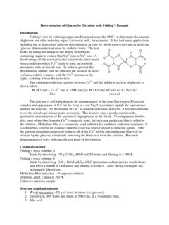
Transcription of B1.1 Determination of Wind Loads for Use in Analysis
1 Determination of wind Loads for Use in Analysis by Tony Gibbs, BSc, DCT(Leeds), FICE, FIStructE, FASCE, FConsE, FRSA November 2000 A PARAMETERS FOR DETERMINING DESIGN wind SPEEDS 1 General wind loading standards provide procedures for determining the Loads on specific structures in specific locations for specific conditions and needs. They start with general (or neutral) conditions and move towards the specific. The neutral data about the wind speeds is usually defined in terms of averaging period, return period, height above ground, topography and ground roughness.
2 Thus, in the OAS/NCST/BAPE "Code of Practice for wind Loads for Structural Design"1 the definition reads: "The basic wind speed V is the 3-second gust speed estimated to be exceeded on the average only once in 50 years .. at a height of 10 m above the ground in an open situation .." The basic (or reference) wind speed is then adjusted for specific cases using various parameters including averaging period, return period, ground roughness, height, topography and size of structure in order to obtain the design wind speeds for the particular cases.
3 In some cases, eg CUBiC2, the apparent starting point for computation is the basic wind pressure. In such cases the basic wind pressure has been predetermined by the standards writer from the basic wind speed. OHPT-13 shows the Basic wind Pressure map from CUBiC. 1 BNS CP28 - Code of Practice for wind Loads for Structural Design; sponsored by the Organization of American States, the National Council for Science & Technology and the Barbados Association of Professional Engineers; prepared by Tony Gibbs, Herbert Browne and Basil Rocheford; November 1981.
4 2 The Caribbean Uniform Building Code 3 Overhead projector transparency number 1 The manner and order in which standards progress from basic wind speeds to design wind speeds differ but, all other things being equal, the end results should be the same. (Of course, all other things are never the same.) 2 Averaging Period Direct measurements of wind speeds are made by anemometers. These instruments vary in the way they sample the wind and in the way they report the results. One of the characteristics of mechanical anemometers is the response time.
5 This is a function of the inertia of the system. The shortest response time for mechanical anemometers is 1-3 seconds. OHPT-2 shows the anemometer record of 3-second gust speeds during the most severe part of Hurricane Georges at V C Bird International Airport in Antigua in 1998. OHPT-3 shows 15-second average wind speeds from a CPACC4 record from St Kitts during the same Hurricane Georges. Several countries have adopted the 3-second gust as the averaging period for the basic wind speed. These countries include Australia, the USA (post 1995)5 and Barbados.
6 The UK used the 3-second gust up to 1995 when they changed to the 1-hour average. A wind speed for any particular averaging period may be converted to a wind speed for any other averaging period using relationships determined experimentally and analytically. These relationships can be presented by a semi-log S curve. OHPT-4 shows the Durst curve which has been in use since the 1960s. In the 1990s Krayer and Marshall proposed an adjusted S curve for tropical cyclone regions. This adjustment was refuted in 1998 by the work of Peter Vickery.
7 At present, therefore, we use the Durst curve for both tropical and extra-tropical cyclones. Public advisories from meteorological offices usually quote sustained wind speeds which, I understand, are meant to be 1-minute averages. The Saffir-Simpson scale is based on these 1-minute averages. OHPT-5 gives the various characteristics of the Saffir-Simpson scale. 3 Return Period wind speeds are amenable to statistical Analysis . It could be argued that the historical record is not sufficiently long for such analyses to be reliable.
8 Nevertheless it is common practice for statistical analyses of historical information, adjusted on theoretical bases, to be used in determining the relative wind -speeds expected to occur over different periods of time. The semi-log graph in OHPT-6 is taken from BNS CP28. It shows relationships for return periods from 2 years to 200 years. The shortest return period (2 years) is recommended for temporary 4 Caribbean Planning for Adaptation to Global Climate Change, tel: (246) 417 4580 5 Some USA codes still use fastest mile wind speeds.
9 These have averaging periods which depend, in turn, on the wind speeds. structures and for (incomplete) structures during erection. The illustration has two sets of curves. The less-severe curve is for the conventional 63% probability level. The more-severe curve is for a 10% probability level. These two curves provide a further opportunity to fine-tune the design for the particular requirements of a project. In general, the longer the return period chosen and the lower the probability level chosen, the more conservative will be the design wind speed.
10 As part of the USAID-OAS Caribbean Disaster Mitigation Project wind speed maps6 have been prepared for the entire Caribbean region. 4 Ground Roughness The roughness of the surface over which the wind passes has two effects on the wind speed and turbulence. The rougher the surface the lower the wind speed but the greater the turbulence. It should be pointed out that so-called smooth flow never occurs. Smooth flow is really a comparative phrase. OHPT-7 shows horizontal and vertical wind speed measurements taken at great height over the Atlantic Ocean east of Barbados during the BOMEX7 project in 1969.