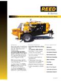
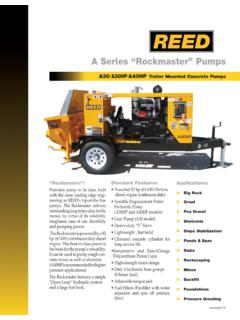
Transcription of B50 TRAILER MOUNTED PUMP MODEL B50 PARTS …
1 TRAILER MOUNTED PUMP MODELB50 ILLUSTRATED part manual B50 PARTSGROUP 00 FIGURE 00 PAGE 01 REED TRAILER MOUNTED CONCRETE PUMP 05 MODEL B50 ILLUSTRATED PARTS manual CONTAINS THE FOLLOWING GROUPS AND FIGURES: GROUP 00 HOW TO USE PARTS manual FIGURE 00 TABLE OF CONTENTS FIGURE 01 HOW TO USE PARTS manual FIGURE 02 HOW TO ORDER PARTS GROUP 10 FINAL INSTALLATION FIGURE 00 TABLE OF CONTENTS FIGURE 01 STANDARD HOPPER WITH SINGLE SHIFT INSTALLATION FIGURE 02 STANDARD HOPPER WITH DUAL SHIFT INSTALLATION FIGURE 03 DECAL ASSEMBLY GROUP 20 HOPPER INSTALLATIONFIGURE 00 TABLE OF CONTENTS FIGURE 01 STANDARD HOPPER INSTALLATION-NO MIXER FIGURE 02 STANDARD HOPPER INSTALLATION-WITH MIXER FIGURE 03 HOPPER CLEAN OUT DOOR ASSEMBLY FIGURE 04 STANDARD HOPPER AGITATOR ASSEMBLY FIGURE 05 STANDARD HOPPER AGITATOR MOTOR ASSEMBLY FIGURE 06 3 SPOOL CONTROL VALVE ASSEMBLY FIGURE 07 3 SPOOL CONTROL VALVE SUB-ASSEMBLY REVISION.
2 TRAILER MOUNTED PUMP MODELB50 ILLUSTRATED part manual B50 PARTSGROUP 00 FIGURE 00 PAGE 02 GROUP 30 TANK INSTALLATION FIGURE 00 TABLE OF CONTENTS FIGURE 01 TANK INSTALLATION FIGURE 02 HYDRAULIC TANK ASSEMBLY FIGURE 03 SWING TUBE CIRCUIT MANIFOLD ASSEMBLY FIGURE 04 SWING TUBE CIRCUIT MAIN SOLENOID VALVE ASSEMBLYFIGURE 05 SWING TUBE CIRCUIT PILOT SOLENOID VALVE ASSEMBLYFIGURE 06 BALL VALVE ASSEMBLY FIGURE 07 DRIVE CYLINDER CIRCUIT MANIFOLD ASSEMBLY FIGURE 08 DRIVE CYLINDER CIRCUIT MAIN SOLENOID VALVE ASSEMBLYFIGURE 09 DRIVE CYLINDER CIRCUIT PILOT SOLENOID VALVE ASSEMBLYFIGURE 10 ACCUMULATOR ASSEMBLY FIGURE 11 ACCUMULATOR BLADDER REPAIR KIT GROUP 40 POWER TRAIN INSTALLATION FIGURE 00 TABLE OF CONTENTS FIGURE 01 POWER TRAIN INSTALLATION FIGURE 02 HYDRAULIC pumps ASSEMBLY FIGURE 03 SINGLE AUXILIARY PUMP ASSEMBLYFIGURE 04 DOUBLE AUXILIARY PUMP ASSEMBLY FIGURE 05 MAIN PUMP ASSEMBLY FIGURE 06 BATTERY MOUNTING ASSEMBLY GROUP 50 CONTROLS INSTALLATION FIGURE 00 TABLE OF CONTENTS FIGURE 01 CONTROLS INSTALLATION FIGURE 02 CONTROL BOX ASSEMBLY FIGURE 03 50 FEET CABLE REMOTE CONTROL ASSEMBLY FIGURE 04 100 FEET CABLE REMOTE CONTROL ASSEMBLY FIGURE 05 RADIO REMOTE CONTROL ASSEMBLY GROUP 60 PUMPING TRAIN INSTALLATIONFIGURE 00 TABLE OF CONTENTS FIGURE 01 SINGLE SHIFT PUMPING TRAIN INSTALLATION FIGURE 02 DUAL SHIFT PUMPING TRAIN INSTALLATION FIGURE 03 SINGLE SHIFT SWING VALVE ASSEMBLY FIGURE 04 DUAL SHIFT SWING VALVE ASSEMBLY FIGURE 05 SINGLE SHIFT SWING RAM CYLINDER SUB-ASSEMBLY FIGURE 06 DUAL SHIFT SWING RAM CYLINDER SUB-ASSEMBLY FIGURE 07 MATERIAL CYLINDER ASSEMBLY FIGURE 08 FLUSHBOX ASSEMBLY FIGURE 09 HYDRAULIC DRIVE CYLINDER ASSEMBLY FIGURE 10 HYDRAULIC DRIVE
3 CYLINDER SUB-ASSEMBLYREVISION: TRAILER MOUNTED PUMP MODELB50 ILLUSTRATED part manual B50 PARTSGROUP 00 FIGURE 00 PAGE 03 GROUP 70 FRAME INSTALLATION FIGURE 00 TABLE OF CONTENTSFIGURE 01 FRAME INSTALLATIONFIGURE 02 HUB AND BRAKE ASSEMBLYFIGURE 03 NON-OPERATOR SIDE ELECTRIC BRAKE ASSEMBLYFIGURE 04 OPERATOR SIDE ELECTRIC BRAKE ASSEMBLYGROUP 80 OPTIONAL INSTALLATIONFIGURE 00 TABLE OF CONTENTSFIGURE 01 OPTIONAL INSTALLATIONFIGURE 02 CENTRALIZED LUBE BLOCK ASSEMBLYFIGURE 03 AUTOLUBE 12 VOLT LUBE PUMP ASSEMBLYFIGURE 04 12 VOLT LUBE PUMP ASSEMBLYFIGURE 05 HOPPER VIBRATOR ASSEMBLYFIGURE 06 ACCUMULATOR CHARGE KITFIGURE 07 OPTIONAL TOOL KIT ASSEMBLYFIGURE 08 SURGE BRAKES ASSEMBLY-PINTLE HITCHFIGURE 09 WATER PUMP INSTALLATIONFIGURE 10 WATER PUMP CONTROL VALVE ASSEMBLYFIGURE 11 WATER PUMP MOTOR ASSEMBLYFIGURE 12 WATER PUMP ASSEMBLYFIGURE 13 NON-OPERATOR SIDE HYDRAULIC BRAKE ASSEMBLYFIGURE 14
4 OPERATOR SIDE HYDRAULIC BRAKE ASSEMBLYFIGURE 15 HYDRAULIC OUTRIGGER CYLINDER ASSEMBLYFIGURE 16 1 SPOOL CONTROL VALVE ASSEMBLYFIGURE 17 1 SPOOL CONTROL VALVE SUB-ASSEMBLYFIGURE 18 2 SPOOL CONTROL VALVE ASSEMBLYFIGURE 19 2 SPOOL CONTROL VALVE SUB-ASSEMBLYFIGURE 20 TIRE & WHEEL ASSEMBLY - ALUMINUMFIGURE 21 50 FEET STROKE COUNTER REMOTE CONTROLLERSHOWN MODEL : STANDARD HOPPER WITH DUALSHIFT SWING CYLINDER UNITREVISION: TRAILER MOUNTED PUMP MODELB50 HOW TO USE part manual B50 PARTSGROUP 00 FIGURE 01 PAGE 01I. PURPOSEThis PARTS manual is prepared, issued and/or revised by REEDM anufacturing, for the exclusive use of its customers and is intended for use in provisioning, requisitioning, storing and issuing replaceable REED TRAILER MOUNTED pump MODEL B50. The contents are proprietary to REEDand are subject to change without notice. The use of any part of this document by any other person or persons or for any other purpose without the written consent of REED is expressly prohibited.
5 In addition, REED expressly disclaims any and all responsibility arising in or any way related to such REED s prior written consent PARTS number content of this document, arrangement and breakdown sequence of items is compatible with Military Standard (MS) and Air Transport Association Specification (ATA).II. GENERAL SYSTEM OF ASSEMBLY ORDER Detailed PARTS List (Refer to Next Page) area refers to the corresponding illustration MODEL GROUP FIGURE PAGE A. MODEL shows which is REED s MODEL number. B. GROUP should be divided with: 00 MODEL B50 PARTS manual 10 FINAL INSTALLATION 20 HOPPER INSTALLATION 30 TANK INSTALLATION 40 POWER TRAIN INSTALLATION 50 CONTROL INSTALLATION 60 PUMPING TRAIN INSTALLATION 70 FRAME INSTALLATION 80 OPTIONAL INSTALLATION C. FIGURE belong to the group. Please see page of contents and each group.
6 D. PAGE numbers follow to the right of each figure number. NUMBER corresponds to the item number shown for the part in illustration. PARTS with item number preceded by a dash (such as: -1, -5, -12 etc.) are not illustrated. 3. PARTS NUMBERS that carry a REED part number. REVISION: TRAILER MOUNTED PUMP MODELB50 HOW TO USE part manual B50 PARTSGROUP 00 FIGURE 01 PAGE 02 REVISION: TRAILER MOUNTED PUMP MODELB50 HOW TO USE part manual B50 PARTSGROUP 00 FIGURE 01 PAGE 03 REVISION: TRAILER MOUNTED PUMP MODELB50 HOW TO USE part manual B50 PARTSGROUP 00 FIGURE 01 PAGE 044. DESCRIPTION SYSTEM used in the PARTS list shows the relationship of one part to another. For a given item, the number of indentures depicts the relationship of the item to the components of the item as follows: 1 2 3 4 5 Assembly (or Installation)x Detail part of assembly x Sub-assemblyx Attaching PARTS for sub-assembly xxDetail part of sub-assembly xxSub-sub-assemblyxxAttaching PARTS for sub-sub-assembly xxxDetail part of sub-sub-assembly xxxSub-sub-sub-assemblyxxxAttaching PARTS of sub-sub-sub-assembly xxxxDetail part of sub-sub-sub-assembly B.
7 See Group 60, Figure 02 For NHA Identifies the illustrated PARTS chapter location; indicates where the Next Higher Assembly (NHA) of the item shown. C. See Group 60, Figure 07 For DET Identifies the illustrated PARTS chapter location; indicates where the item and its Detailed Breakdown (DET) is shown. D. See Group 30, Figure 05 for REF or See Vendor Chapter For REF Identifies the illustrated PARTS chapter where the part is, and if listed and illustrated in Vendor Chapter. It is used as a cross-reference (REF).5. QUANTITY (REF) indicates the items that is listed previously in the Next Higher Assembly (NHA) and then again in this figure. Required (A/R) indicates the PARTS that is used in a quantity as required. number entry indicates the quantity of the part used in its next higher application. 6. Functionally related assemblies are illustrated in phantom ( )but not listed on the detail PARTS list page.
8 REVISION: TRAILER MOUNTED PUMP MODELB50 HOW TO ORDER PARTS B50 PARTSGROUP 00 FIGURE 02 PAGE 011. Always give serial number and MODEL ofREED TRAILER MOUNTED concrete pump05 MODEL B50. (Refer to each unit name plate shown below). NOTE: This manual is being released to cover unit starting with serial number3-07-1-2754to current production. Some components used on earlier units differ from current productions. Where this occurs, the part is identified by a serial Always specify part number and complete name of PARTS ordered. to table of content in the desired Installation. Refer to main group in which part should be listed. B. Find title of figure in which the part should be shown. Note figure : TRAILER MOUNTED PUMP MODELB50 HOW TO ORDER PARTS B50 PARTSGROUP 00 FIGURE 02 PAGE to corresponding page, find the group and figure.
9 D. Check your required part and its attaching PARTS and match with illustration page. to corresponding item number in the part list page. part numbers are located in the part number column. F. When ordering variable or optional miscellaneous PARTS which are not found this in PARTS chapter, follow the above outlined procedure of how to order PARTS . 1).When applicable, give MODEL and serial number of the component for which PARTS are desired. 2).In a specific, difficult to describe situation, a marked-up photograph or detailed sketch would be : TRAILER MOUNTED PUMP MODELB50 HOW TO ORDER PARTS B50 PARTSGROUP 00 FIGURE 02 PAGE 033. Do not designate quantity by set . State specifically how many PARTS are wanted. 4. Always give complete address and full shipping instructions. Specify shipping instructions, truck freight, air freight. United Parcel Service (UPS), or FedEx and DHL are available in designated areas.
10 5. TO ORDER A. BY MAIL Attention: PARTS Department REED 13822 Oaks Avenue Chino, CA. 91710 B. BY FAX (909) 287 - 2141 C. BY PHONE (909) 287 - 2100 6. PARTS return without authorization will not be accepted. If it is necessary to return PARTS for any reason, written authorization may be obtained from REED PARTS Department, Chino, CA. 91710. A PARTS Return Authorization form is provided whenREED deems its necessary to have the part returned for evaluation. The form is issued by the Warranty of PARTS Department of The form will be filled by REED unless requesting necessary information and you will receive a copy as well as shipping tag. shipping tag to part insert return original invoice. C. Ship part to REED must be returned to REED within 30 days from date of : TRAILER MOUNTED PUMP MODELB50 GROUP 10 FINAL INSTALLATION B50 PARTSGROUP 10 FIGURE 00 PAGE 01 REED TRAILER MOUNTED CONCRETE PUMP 05 MODEL B50 ILLUSTRATEDPARTS manual GROUP 10 FINAL INSTALLATION CONTAINS THE FOLLOWING FIGURES:FIGURE 00 TABLE OF CONTENTS FIGURE 01 STANDARD HOPPER WITH SINGLE SHIFT INSTALLATION FIGURE 02 STANDARD HOPPER WITH DUAL SHIFT INSTALLATION FIGURE 03 DECAL ASSEMBLYREVISION:STANDARD HOPPER WITH SINGLE SHIFT FINAL INSTALLATION B50 PARTSGROUP 10 FIGURE 01 PAGE 01 REVISION.
