Transcription of BACK TO BASICS: DUCT DESIGN - AIRAH - Home
1 Matthew Low, , CPEng 15 MAY 2013 back TO basics : duct DESIGN back to basics : duct DESIGN Quick Introduction duct Sizing Tools and Methods Recommended duct Velocities and Noise Effects duct Fitting Pressure Losses Do and Don ts of duct DESIGN duct Applications AS 4254 Quick Introduction A Good duct DESIGN is a balance between Application ( DESIGN Intent) Reliability (Maintenance Cost) Manufacturing Costs (Capital Cost) Pressure Loss (Operational and Energy Cost) Acoustics (Environmental Cost) Air Balancing (Commissioning Cost) duct Sizing Tools OR duct Sizing Chart Ductulator (Manual/Digital) AIRAH DA3 duct DESIGN Manual Manufacturers/Programs duct Sizing Methods Methods Description Summary Pros Cons Velocity Reduction Base on Experience Q=VA (Continuity equation) Simplest Not standard Not completely balanced Constant Pressure Gradient Also called Equal Friction In Pa/m Straight duct Higher Pa/m used Very Simple Considerable dampening required Static Regain Supply air only Decrease in velocity pressure branch or fitting Offsets friction loss in succeeding section of duct Fixing 1st Segment with methods above Lower system pressure loss Lower Energy consumption Less Noise issues in take offs Larger duct sizes Increased capital cost Increased spatial requirements Balanced Pressure Drop Any method above initially Determine the index run Resize to ensure pressure loss similar to index Better pressure balanced system Small duct sizes Reduced capital and spatial costs Tedious Calculations Higher velocities at take offs may be noisy Dampering of Larger ducts may be as or more noisy T-Optimisation ASHRAE Fundamentals Operation and Capital Cost
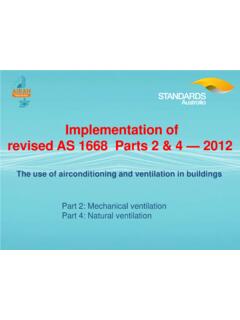
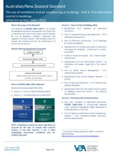
2 Optimisation focused Simple Best Economical Sizing Method Very tedious calculations with simulations Spatial costs neglected Recommended duct Velocities and Noise Effects Table above shows the duct velocities based on AES project experience HOWEVER, Project/ DESIGN Engineer must always check and select appropriate sizes to suit the project s complexity and application duct Fitting Pressure Loss Various duct fitting pressure losses AIRAH DA3 or the AIRAH Technical Handbook More available in the ASHRAE Handbook or SMACNA Obtain other duct fittings pressure losses from manufacturers such as duct heaters, dampers, filters, grilles, coils, etc Calculated by the following formula (derived from Bernoulli s) PTOTAL = KT X PV = KT X X V2 PTOTAL = the total pressure loss across the duct fitting KT = the pressure loss coefficient of duct fitting Pv = velocity pressure (dynamic pressure) = density of air V = velocity of fluid Example of duct Fitting Loss Vu = Upstream velocity of fitting H = Height of the duct W = Width of the duct R = Radius of the bend = Angle of the radius Calculate the pressure loss of the duct fitting in a 600mm W x 200mm H duct with a radius of 600mm and a 90 Bend angle.
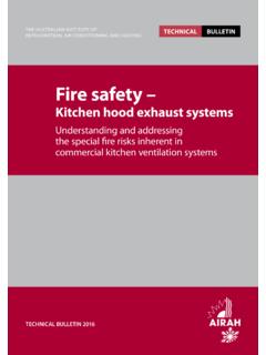
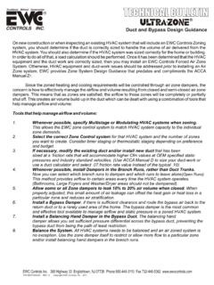
3 Say Reynolds number as 4500. Therefore the pressure loss is Example of an AES Static Calculation Sheet Can be summarised in a spreadsheet Remember to include other manufacturer s type ancillary duct fittings like duct heaters, VAVs, coils, etc Total static pressure safety various on application Installation Do s and Don ts Good resource - Fans by Fantech Book Installation Do s and Don ts by Fantech duct Applications Kitchen Exhaust Ductwork Smoke Exhaust Ductwork Seismic Restraining Winds Restraining (not covered in this presentation) Acoustics and Attenuation (refer to back to basics : Acoustics held last Technical Meeting) Etc Kitchen Exhaust Ductwork Construction of or stainless as per AS1668 standard with Seams sealed to prevent grease leakage. Spigot connections at 5 to 7m/s. duct to slope up in direction of flow for grease flow back to hood. duct access panels every 3 metres of straight duct and change of direction.
4 Builder/Architect must provide access panels. Lower edge of canopy type must not be less than 2m above floor level at the operator side of cooking equipment. Smoke Exhaust Ductwork Internal insulated smoke exhaust ductwork must have perforated metal lining Coated with fire rated spraying/wrapping, cladding and etc must applied where smoke exhaust ductwork in a different fire compartment it serves Construction of galvanised steel or stainless steel thick ductwork. Subducts are 2mm ductwork and fully welded at each level to prevent smoke migration between non fire affected floors. Riser shafts adequately sized to allow for restrictions. Refer to for additional Seismic Restraints Requirements determined by AS and not clear in DESIGN documents. Building Structural Engineer and Building Certifier to classify the following:- Earthquake DESIGN Category Building Importance Probability of Exceedance of DESIGN events and Probability factor Hazard Factor Site Sub Soil Classification duct installed to be reviewed initially and finally by structural engineer (project or independent) prior to completion AS4254: duct Classification Standard duct pressure classification tables found in the AS 4254 such as low, medium or high pressure AS4254 explains duct thicknesses, sealing, reinforcement and functional requirements.
5 Refer to table for duct thicknesses and reinforcement methods Changes to 2012 edition as follows: Fire rated duct must be constructed to the same standard as the tested solution for that particular product. Detail must be obtained from the relevant supplier at the start of the project and may be different depending on the proposed fire rating method. Any duct system over 3000 L/s must be tested at minimum 10% of each system at times operating pressure. Thank You