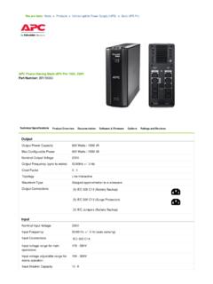
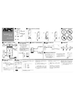
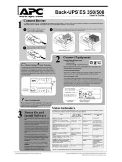
Transcription of Back-UPS Pro 1000 Installation and Operation
1 Back-UPS Pro 1000 Installation and OperationConnect the batteryInstall PowerChute Personal Edition SoftwareAPC PowerChute Personal Edition software provides automatic file saving and shutdown of your computer in the event of a power failure. Use the cable supplied with the Back-UPS to connect the data port on the Back-UPS to the USB port on your computer. Place the CD into your computer, and follow the on-screen not install the Back-UPS in direct sunlight, in excessive heat, humidity, or in contact with fluids. bu001bbu055abu057abu059abu058abu060aBack -UPS Pro 1000 Installation and Operation2 Connect the equipmentBattery Backup and Surge Protected outletsWhen the Back-UPS is receiving input power, the Battery Backup with Surge Protection outlets will supply power to connected equipment. During a power outage or other utility problems, the Battery Backup outlets receive power for a limited time from the Back-UPS .
2 Connect equipment such as printers, fax machines, scanners, or other peripherals that do not need battery backup power to the Surge Protection Only outlets. These outlets provide full-time protection from surges even if the Back-UPS is switched OFF. Master and Controlled outletsTo conserve electricity, when the device connected to Master Outlet goes into Sleep or Standby mode, or turns Off, the Controlled device(s) will shut down as well, saving electricity. Connect a master device, such as a desktop computer or audio/visual receiver to the Master outlet. Connect peripheral devices such as a printer, speakers, or a scanner to the Controlled outlets. USB and Serial Data portTo use PowerChute Personal Edition, connect the supplied USB software cable or serial cable (available separately). Ground screwConnect the ground lead of additional surge suppression devices such as network and data line surge protectors. Building Wiring Fault indicatorIf this indicator is illuminated, there is a problem with the wiring in the building.
3 Contact an electrician immediately and do not use the Back-UPS . Surge Protected outlets, controlled by the Master outletThese outlets are protected from electrical surges, and will disconnect from utility power during a power outage, or if the Master device goes into Sleep or Standby mode. Surge Protected outletsThese outlets provide full-time protection from surges, even if the Back-UPS is off. Connect equipment such as printers and scanners that do not require battery backup protection. Battery Backup outlets with Surge ProtectionDuring a power outage or other utility problems, the Battery Backup outlets receive power for a limited time from the Back-UPS . Connect critical equipment such as desktop computer, computer monitor, modem or other data sensitive devices into these outlets. Battery Backup outlets with Surge Protection, controlled by the Master outletThese outlets will supply battery power to the connected equipment during a power outage.
4 Power will be disconnected to these outlets if the Master device goes into Sleep or Standby mode. Connect equipment such as a computer monitor to these outlets. Master outletConnect the master device to this outlet, in most scenarios, this will be the main computer. In & Out Ethernet surge-protected portsUse an Ethernet cable to connect a cable modem to the IN port, and connect a computer to the OUT port. Co-axial ports with surge protectionConnect a cable modem or other equipment with coaxial Pro 1000 Installation and Operation3 OperationPower-Saving FunctionTo conserve electricity, configure the Back-UPS to recognize a Master device, such as a desktop computer or an A/V receiver, and Controlled peripheral devices, such as a printer, speakers, or a scanner. When the Master device goes into Sleep or Standby mode, or is switched OFF, the Controlled device(s) will be switched off as well, saving the Power-Saving function.
5 Press and hold MUTE and DISPLAY simultaneously for two seconds. The Back-UPS will beep to indicate that the feature is enabled. The leaf icon on the display will the Power-Saving function. Press and hold MUTE and DISPLAY simultaneously for two seconds. The Back-UPS will beep to indicate that the feature is disabled. The leaf icon on the display will the threshold. The amount of power used by a device in Sleep or Standby mode varies between devices. It may be necessary to adjust the threshold at which the Master outlet signals the Controlled outlets to shut Ensure a master device is connected to the Master outlet. Put that device into Sleep or Standby mode, or turn it Press DISPLAY and MUTE simultaneously and hold for six seconds, until the leaf icon flashes three times and the Back-UPS beeps three The Back-UPS will now recognize the threshold level of the Master device and save it as the new threshold Display The display interface can be configured to be continuously illuminated, or to save energy, it can be configured to darken after a period of Full Time Mode: Press and hold DISPLAY for two seconds.
6 The display will illuminate and the Back-UPS will beep to confirm the Full-Time mode. 2. Power-Saving Mode: Press and hold DISPLAY for two seconds. The display will darken and the Back-UPS will beep to confirm the Power-Saving mode. While in Power-Saving Mode, the display will illuminate if a button is pressed, it then darkens after 60 seconds of no activity. Unit sensitivity Adjust the sensitivity of the Back-UPS to control when it will switch to battery power; the higher the sensitivity, the more often the Back-UPS will switch to battery power. 1. Ensure the Back-UPS is connected to utility power, but is Press and hold the POWER button for six seconds. The LOAD CAPACITY bar will flash on and off, indicating that the Back-UPS is in programming Press POWER again to rotate through the menu options. Stop at selected sensitivity. The Back-UPS will beep to confirm the SensitivityDefaultSensitive LoadsLow sensitivityMedium sensitivity (Default)High sensitivity78-142 Vac88-139 Vac88-136 VacInput voltage is extremely low or high.
7 (Not recommended for computer loads.)The Back-UPS frequently switches to battery connected equipment is sensitive to voltage Pro 1000 Installation and Operation4 Front Panel Buttons and Display InterfaceUse the three buttons on the front panel of the Back-UPS and the display interface to configure the panel Mute button Power On/Off button Display button Display interfaceOn Line The Back-UPS is supplying conditioned utility power to connected equipmentPower-Saving Master and Controlled outlets are enabled, saving power when the master device goes into sleep or standby modeLoad Capacity The load is indicated by the number of sections illuminated, one to five. Each bar represents 20% of the Charge The battery charge level is indicated by the number of sections illuminated. When all five blocks are illuminated, the Back-UPS is at full charge. When one block is filled, the Back-UPS is near the end of its battery capacity, the indicator will flash and the Back-UPS will beep The power demand from the load has exceeded the capacity of the The event counter shows the number of events that occurred that caused the Back-UPS to switch to on-battery Voltage Regulation The Back-UPS can compensate for high or low input illuminated, the Back-UPS is compensating for low input illuminated, the Back-UPS is compensating for high input Input Output Faults The system has a fault.
8 The fault number will illuminate on the display interface. See System Faults on page If the line through the speaker icon is illuminated, the audible alarm has been turned Battery The battery is not connected or is nearing the end of its useful life. Replace the Battery The Back-UPS is supplying battery backup power to the connected equipment, it will beep four times every 30 Pro 1000 Installation and Operation5 Warnings and System FaultsAudible WarningsWarning IconsSystem FaultsThe Back-UPS will display these fault messages. For faults F01 and F02, contact APC Technical Beeps Every 30 SecondsBack-UPS is running on battery. You should consider saving any work in Beeping Low battery condition and battery run-time is very low. Promptly save any work in progress, exit all open applications, and shut down the operating toneBattery Backup outputs are overloaded. Chirps for 1 Minute every 5 hoursBattery fails the automatic diagnostic test and should be these icons are may be the Back-UPS is operating on utility power, but is overloaded.
9 Disconnect one of the items connected to the Back-UPS . If the Overload icon stops flashing, the Back-UPS is no longer overloaded and will continue to operate Back-UPS is operating on battery power, but is overloaded. Disconnect one of the items connected to the Back-UPS . If the Overload icon stops flashing, the Back-UPS is no longer overloaded and will continue to operate Back-UPS is operating on utility power, but the battery is not functioning properly. Contact APC Customer Service to order a replacement battery. See Replacement Battery on page Back-UPS is operating on battery power and the battery power is getting low. Shut down all connected equipment to avoid losing an unsaved data. When possible, connect the Back-UPS to utility power to recharge the OverloadTurn the Back-UPS off. Disconnect non-essential equipment from the Battery Backup outlets and the turn Back-UPS Output ShortTurn the Back-UPS off.
10 Disconnect non-essential equipment from the Battery Backup outlets and the turn Back-UPS Xcap OverloadFaults F03-F09 cannot be corrected by the user, contact APC Technical Support for ShortF05 Charge FaultF06 Relay WeldingF07 TemperatureF08 Fan FaultF09 Internal Faultbu088aBack-UPS Pro 1000 Installation and Operation6 Function Button Quick-Reference FunctionButtonTiming (seconds)UPS StatusDescriptionPowerPower POWER to start receiving input utility power. If A/C input power is not available, the Back-UPS will run on battery Off2 OnThe Back-UPS is not receiving input utility power, but is providing surge the status or condition of the Back-UPS . The LCD will illuminate for 60 mode2 OnThe LCD will illuminate and the Back-UPS will beep to confirm the Full-Time mode. The LCD will darken and the Back-UPS will beep to confirm the Power-Saving mode. While in Power-Saving Mode, the LCD will illuminate if a button is pressed, then darkens after 60 seconds of no any audible alarms caused by an Status Enable/Disable2 OnEnable or disable the audible alarms.