Transcription of Ball Valves, Floa• ng Ball Design F14D Class PN 10 …
1 ball valves , Floa ng ball Design6 f14d - Class PN 10 - 16 - 25 - 40 Carbon Steel ball valves Full port, Split body, Side entry designFeatures An! sta! c device Blowout-proof stem High performance PTFE ball seats Actuator moun! ng pad to ISO 5211 Standards: Design : EN 1983:2006 Thickness: EN 12516-1 Flanges drilled: EN 1092 Flanges surfaces: EN 1092 Dimensions of PN 10 -16 - 25 - 40 f14d Un: mmClassDNPNGear OperatorHP1 BAValve Size (Dn)10016-40-30028271125-30028271150-300 282712003424003408625010-163784003408625 -40378500365130300 10-40440500365130 Gear Opera!
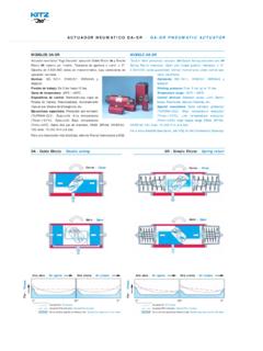
2 On Un: mm Worm gear operators may be mounted on KITZ ball valves at your op! on for the smoothest valve opera! on. Electric or pneuma! c actuators are also op! onally available. Contact KITZ distributors for appropriate choice and sizing of valve test: BS EN 12266-1 Class A & DIN 3230 FSM: BS 6755 P2 Lengths: Distance between fl anges as per EN 558-1DN 100 basic serie 14 (Short)DN 125 basic serie 15 (Short) - Serie 1 (Long) Page 3 for Pressure-Temperature Ra! ngsPage 7 for Construc! on and Materials Page 10 for Dimension of Actuator Moun!
3 Ng Pad*1 PN 25-40: ball Bore=95X= 85H=190*2 PN 25-40:P=750*3 PN 25-40:H=396*4 Gear Box includedValve SizeDNPortLXPHISO5211Cv (m /h)Torque ( )Weight (Kg)PN10-16PN25-40 ShortLongPN16PN40 ShortLongShortLong15141151305015085F0317 582,62,82,62,820191201505215090F0339683, 33,63,33,6252512516055150104F05638104,34 ,54,34,5323213018058200116F0510415206,56 ,76,56,7403814020060200118F0515020257,87 ,97,87,9505115023060250128F07254253511,9 12,511,912,5656517029075250138F073814050 1516,115,516,5807618031078250148F0797160 902022,52123100 (1)10219035095500196F1015601201753339,63 4,540,2125 (2) ,585200190400-200-Gear opera!
4 OnF148787500750175 (4)-185 (4)-250 (3)241450-225-Gear opera! onF141445210001400230 (4)-250 (4)-300285500-250-Gear opera! onF162289315002000305 (4)-370 (4)-1 Cv = 1,16 KvValve OperatorDn 15 150 : lever opera! onDn 100 150 : op! onal gear box Dn 200 : gear box or lever (op! onal)Torque ValuesThe values shown are an average of the real values. These values have been taken under ideal condi! ons of clean water, room temperature, standard seats, daily handling and without safety valves , Floa ng ball Design7 Construc on and 10 - 16 - 25 - 401 BodyDIN Body ConnectorDIN An sta c Stem*1 ASTM A479 Type 316 / 4106 Gland RingASTM A479 Type 3168 Stop PinSteel9 Stop PlateSteel zinc plated11 Gland WasherSteel zinc plated12 NutDIN 267/3-8 blued17 Stud Bolt-BoltDIN 267/3/4 C / zinc plated18 NutDIN 267/3/4 C / zinc plated21 ball *2 ASTM A479 Type 316/CA15 / DIN ball SeatPTFE24 Body Seal*4 PTFE / 316L+ Flexite 25 Gland Packing*3 PTFE+C+Graphite / PTFE26 Stem Seal*5 PTFE+C+Graphite / PTFE30 HandleSteel coated31 Handle
5 HeadGGG4032 Handle barGGG4033 Handle bar boltStainless Steel35 BoltSteel36 WasherSteel40 Stem O ringFKM Standard material confi gura on can be applied to sour part numbers are corresponding with those shown in valve assembly drawings.*1 DN 50 : ASTM A479 Type 31650 < DN < 250 :ASTM A479 Type 410 DN 250 :ASTM A479 Type 316*2 DN 50:ASTM A479 Type 31650 < DN < 250 :ASTM A217/A743 Gr.
6 CA15 DIN (Op onal)DN 250 :DIN *3 DN 25 :PTFE+C+GraphiteDN > 25:PTFECod. FSM:Graphite (Op onal)*4 DN 25 :PTFEDN > 25 :316L+ Flexite Cod. FSM :316L+Graphite (Op onal)*5 DN 25 :PTFE+C+GraphiteDN > 25 :PTFE DN 25 Valve fi nish : phosphate and oil on group :DN 150:by lever. (100 ~150 op on: gear box)DN = 200: by gear box or with lever (Op onal)DN > 200: by gear valves , Floa ng ball Design8 f14d - Class PN 10 - 16 - 25 - 40 Stainless Steel ball valves Dimensions of PN 10-16 - 25 - 40 f14d Un: mmClassDNPNGear OperatorHP1 BAValve Size (Dn)10016-40-30028271125-30028271150-300 282712003424003408625010-163784003408625 -40378500365130300 10-40440500365130 Gear Opera!
7 On Un: mm Worm gear operators may be mounted on KITZ ball valves at your op! on for the smoothest valve opera! on. Electric or pneuma! c actuators are also op! onally available. Contact KITZ distributors for appropriate choice and sizing of valve actuators.*1 PN 25-40: ball Bore=95X= 85H=190*2 PN 25-40:P=750*3 PN 25-40:H=396*4 Gear Box included1 Cv = 1,16 KvValve SizeDNPortLXPHISO5211Cv(m /h)Torque ( )Weight (Kg)PN10-16PN25-40 ShortLongPN16PN40 ShortLongShortLong15141151305015085F0317 582,62,82,62,820191201505215090F0339683, 33,63,33,6252512516055150104F05638104,34 ,54,34,5323213018058200116F0510415206,56 ,76,56,7403814020060200118F0515020257,87 ,97,87,9505115023060250128F07254253511,9 12,511,912,5656517029075250138F073814050 1516,115,516,5807618031078250148F0797160 902022,52123100 (1)10219035095500196F1015601201753339,63 4,541125 (2) ,585200190400-200-Gear opera!
8 OnF148787500750175 (4)-185 (4)-250 (3)241450-225-Gear opera! onF141445210001400230 (4)-250 (4)-300285500-250-Gear opera! onF162289315002000305 (4)-370 (4)-Valve OperatorDn 15 150 : lever opera! onDn 100 150 : op! onal gear box Dn 200 : gear box or lever (op! onal)Features An! sta! c device Blowout-proof stem High performance PTFE ball seats Actuator moun! ng pad to ISO 5211 Standards: Design : EN 1983:2006 Thickness: EN 12516-1 Flanges drilled: EN 1092 Flanges surfaces: EN 1092 Leak test: BS EN 12266-1 Class A & DIN 3230 FSM: BS 6755 P2 Lengths: Distance between fl anges as per EN 558-1DN 100 basic serie 14 (Short)DN 125 basic serie 15 (Short) - Serie 1 (Long) Page 3 for Pressure-Temperature Ra!
9 NgsPage 9 for Construc! on and Materials Page 10 for Dimension of Actuator Moun! ng PadFull port, Split body, Side entry designTorque ValuesThe values shown are an average of the real values. These values have been taken under ideal condi! ons of clean water, room temperature, standard seats, daily handling and without safety valves , Floa ng ball Design9 Construc on and 10 - 16 - 25 - 401 BodyDIN Body ConnectorDIN An sta c StemASTM A479 Type 3166 Gland RingASTM A479 Type 3168 Stop PinDIN 267/11 A2-709 Stop PlateSteel nickel plated11 Gland WasherDIN (SS)
10 12 NutDIN 267/11 A2-7017 Stud Bolt-Bolt*5 DIN 267/11/ A2-70 / 267/3 zinc plated18 Nut*5 DIN 267/11/ A2-70 / 267/3 zinc plated21 ball *1 ASTM A479 Type 316 / ball SeatPTFE24 Body Seal*3 PTFE / 316L+Flexite 25 Gland Packing*2 PTFE+C+Graphite / PTFE26 Stem Seal*4 PTFE+C+Graphite / PTFE30 HandleSS+Plas c31 Handle headGGG4032 Handle barGGG4033 Handle bar boltStainless Steel35 BoltStainless Steel36 WasherStainless Steel40 Stem O ringFKM Standard material confi gura on can be applied to sour part numbers are corresponding with those shown in valve assembly drawings.