Transcription of BAROMETRIC PRESSURE SENSOR OPERATION MANUAL …
1 102663-9800 PRESSURE SENSOR Rev ISO 9001:2000 Certified BAROMETRIC PRESSURE SENSOR OPERATION MANUAL P/N 102663 Main Office: 140 Wilbur Place Bohemia, NY 11716 631-567-7300 (P) 631-567-7585 (F) West Coast Service: 1600 NW Washington Blvd. Grants Pass , OR 97526 541-471-7111 (P) 542-471-7716 (F) Central Regional Service: 3206 Main St. Suite 106 Rowlett, TX 75088 972-412-4715 (P) 972-412-4716 (F) Page 2 ISO 9001:2000 Certified Technical Support Thank you for choosing a Climatronics product and we sincerely appreciate your interest and expectation in using it. Should you require support during initial setup and OPERATION , please consult this printed documentation to resolve your problem. If you are still experiencing difficulty, you may contact a Technical Service representative during normal business hours 7:30 to 4:00 Eastern Time, Monday through Friday.
2 Voice: (631) 567-7300 Fax: (631) 567-7585 E-Mail: Mail: Technical Services Department Climatronics Corp. 140 Wilbur Place Bohemia, NY 11716 Page 3 ISO 9001:2000 Certified Safety Notice The contents of this MANUAL have been checked against the hardware and software described herein. Since deviations cannot be prevented entirely, we cannot guarantee full agreement. However, the data in this MANUAL is reviewed regularly and any necessary corrections are included in subsequent editions. Faultless and safe OPERATION of the product presupposes proper transportation, storage, and installation as well as careful OPERATION and maintenance. The seller of this equipment cannot foresee all possible modes of OPERATION in which the user may attempt to utilize this instrumentation.
3 The user assumes all liability associated with the use of this instrumentation. The seller further disclaims any responsibility for consequential damages. Electrical & Safety Conformity The manufacturer certifies that this product operates in compliance with the following standards and regulations: FDA/CDRH This product is tested and complies with 21 CFR, Subchapter J, of the Health and Safety Act of 1968 US 21 CFR Warranty All instruments are warranted against defects in parts or workmanship for a period of two (2) years from the date of shipment. Should any instrument or part prove to be defective within the warranty period, upon written notice and return of the unit (freight prepaid), Climatronics Corporation will, at its option, repair or replace the defective unit, and return it, transportation prepaid via UPS.
4 Equipment abused, modified, or altered may cause cancellation of this warranty. The above warranty applies only to items manufactured by Climatronics Corporation. Items not manufactured by Climatronics Corporation are warranted only to the extent and in the manner warranted by the manufacturer of such items. Should emergency warranty repair be required at a customer's facility, Climatronics will provide such repairs and charge only the portal-to-portal Field Service rates and actual expenses in accordance with our published rates then in effect. Expendable supplies and wear items, such as bearings and lightning- related damages, are not covered under this warranty. Page 4 ISO 9001:2000 Certified Table of Contents SAFETY .. 5 INTRODUCTION & OVERVIEW BAROMETRIC PRESSURE 6 6 7 INSTALLATION.
5 8 MOUNTING FOR OUTDOOR 8 MOUNTING FOR INDOOR 9 INPUT/OUTPUT 9 USER 10 CALIBRATION .. 11 MAINTENANCE .. 11 CONTROL AND COMMUNICATION .. 11 APPENDIX A - TERMINAL MODE AND SDI 12 SDI-12 APPENDIX B - THEORY OF 15 APPENDIX C - WIRING .. 17 Page 5 ISO 9001:2000 Certified Safety Safety This MANUAL may include a CAUTION and a WARNING indication. Familiarize yourself with the following definitions for the meanings of these indicators. A CAUTION indicates a hazard and calls attention to a procedure that if not correctly followed could result in damage to the instrument. Do not proceed beyond a caution indicator without understanding the hazard. A WARNING indicates a hazard to you and calls attention to a procedure that if not correctly followed could result in injury or even death.
6 Do not proceed beyond a warning without understanding the hazard. Page 6 ISO 9001:2000 Certified Introduction & Overview BAROMETRIC PRESSURE SENSOR Overview The 102663 BAROMETRIC PRESSURE SENSOR is designed to measure ambient atmospheric PRESSURE and provide serial digital outputs and analog outputs all from the same SENSOR module. PRESSURE is sensed using a board mounted digital PRESSURE SENSOR . An on board CPU scales PRESSURE measurement and performs communications. The 102663 is simple to set up and use. The analog output voltage and PRESSURE range limits are set with DIP switches. The DIP switches allow quick configuration without requiring a laptop or data-logger for communication. Additional parameters may be configured with a terminal connection (see section 10). The terminal connection accommodates standard RS-232 and RS-485.
7 The SDI-12 interface parameters may be configured using an SDI-12 master in the transparent mode. Consult the MANUAL for your particular datalogger for additional information. Page 7 ISO 9001:2000 Certified Specifications Operational Range: 600-1100 mbar ( in Hg) Resolution: mbar (.003 Hg) Temp. Operating Range: -40 to +55 C Temp. Compensated Range: -40 to +55 C Accuracy: mbar @ +25 C mbar @ 0 to +55 C mbar @ -40 C Long Term Stability: 1 mbar in 12 months Analog Output 0 1, 0 2, , or 0-5 VDC (Analog output automatically adjusts to zero to full scale for range selected. Default output = 0-5 VDC, 800-1100 mbar) Digital Outputs RS-232 RS-485 SDI-12 (Default address = 0) Communications Protocol Terminal mode and for RS-232 and RS485 SDI-12 Serial Settings Baud options = 1200, 2400, 4800, 9600, 19200; 8 data bits, no parity, and 1 stop bit.
8 Default baud rate = 19200 Power 10-36 VDC, 10 ma @ 12 VDC Connections Screw terminals on circuit board Size Polycarbonate Enclosure x x inches (120 x 80 x 55 mm) *Analog output range set with DIP switches, lower range settings 600, 700, 800, 900 mbar, upper range settings 800, 900, 1000, 1100 (Invalid DIP switch settings produce 600-1100 mbar range. Default range = 800-1100 mbar.) Page 8 ISO 9001:2000 Certified Installation The SENSOR is designed for indoor or outdoor use. Refer to Figures and for mounting dimensions. Mounting for Outdoor Use When designated for outdoor use, the unit is supplied with a solar shield and U-bolts. The SENSOR is provided attached to the solar shield. Install the solar shield with the U-bolts provided on any vertical pipe up to 2 IPS. For mounting on a flat surface, remove U-bolts.
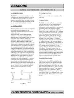
9 Refer to Figure for mounting dimensions. Install the SENSOR to face a northerly direction so that the solar shield protects the SENSOR enclosure from direct sunlight. Figure Page 9 ISO 9001:2000 Certified Mounting for Indoor Use For indoor mounting to a flat surface without the solar shield, refer to Figure for mounting dimensions. Please note, the cover must be removed to access the mounting holes when mounting the PRESSURE SENSOR in this manner. It is important to replace the cover after mounting. PRESSURE SENSOR module is light sensitive and will not operate properly if cover is removed. Figure Input/Output Connections See Appendix C for wiring details. Figure , 102663-1 and 102663-2: Analog, SDI-12, and RS232 outputs (Standard wiring). Alternate RS485 wiring shown by dashed lines.
10 Figure , 102663-3: Optional Analog output. Caution: All outputs, Analog, SDI-12, RS232, and RS485 have voltage on them. If any live outputs are not being used, these wires should be properly protected so as not to short to ground or any other wires. Note: Be sure to replace cover after any wiring changes. PRESSURE SENSOR module is light sensitive and will not operate properly if cover is removed. Page 10 ISO 9001:2000 Certified User Interface SW1-Analog Output Switch Settings Range SW1-1 SW1-2 0-1 V On On 0-2 V On Off V Off On 0-5 V Off Off SW2 - PRESSURE Range Switch Settings Lower Range Upper Range SW2-1 SW2-2 SW2-3 SW2-4 600 800 On On On On 600 900 Off On On On 600 1000 On Off On On 600 1100 Off Off On On 700 800 On On Off On 700 900 Off On Off On 700 1000 On Off Off On 700 1100 Off Off Off