Transcription of Basic Active and Passive Filters - surflibrary.org
1 Basic Active and Passive Filters Bruce C. Gabrielson, PhD. Security Engineering services 5005 Bayside Rd. Chesapeake Beach, MD 20732. Introduction Regardless of the specific electromagnetic discipline involved, an understanding of Basic filter design techniques and applications is essential for reducing emission (and resulting radiation). problems. Passive or Active Filters are used to reduce conducted emissions on powerlines, signal lines, and control lines, as well as for decoupling protection between noisy circuit components. Therefore, depending on application, Filters can be considered as containment or as source suppression components. This paper first revisits Basic filter theory, then examines typical emission controlled or low noise applications for both Active and Passive filtering. Filters using ferrite bead materials on signal lines will not be addressed. Basic Theory Filters (absorptive or reflective) are used to pass signals or currents at certain frequencies to the intended load, while shunting unwanted frequencies to ground or sending them back to their source.
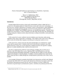
2 Passive Filters use an inductive impedance and a capacitive impedance to achieve filtering capabilities, while Active Filters rely on resistive capacitive networks.+. Common Passive Filters are normally constructed in three network configurations, L, T, and Pi. The L network is the simplest, with the impedances connected as single components. The T. network splits the series impedance in half, with half placed before and half after the shunt impedance. The Pi network splits the shunt impedance in half, with half placed before and half after the series impedance. Filters are generally classified in terms of their response characteristics (shown in Figure 1) as high pass, low pass, band reject, and band pass. Highpass Filters are characterized by a high impedance below cutoff frequency, passing all signals above that frequency. Highpass Filters are commonly used to remove signals induced by power line noise from signal lines.
3 This filter type is typically used for EMI rather then emission controlled problems. Bandpass Filters are characterized by a low impedance at a specified frequency band, with significantly higher impedances below and above that band. Typical emission controlled applications include equipment that handles frequency-division multiplexing, such as voice-frequency telegraph terminals, to control individual channels. Band reject Filters create a high impedance in the frequency band of interest. While seldom used in Emission controlled applications, primarily because problem frequencies often appear over a 1. large range of harmonics, they can be employed in selected applications involving a fundamental circuit resonant frequency, or in special RED/BLACK interface situations. Figure 1 - filter Response Characteristics For most emission controlled powerline and signal line applications, low pass Filters are normally employed.
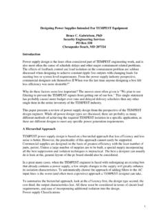
4 This filter type passes the signal or current below a specified frequency and attenuate all signals above that point. Since problem signals often appear as harmonics well above their fundamental RED line frequency, and since modulation schemes can create problem signals on carriers existing at frequencies significantly higher then the Red line source, low pass Filters are most commonly employed for emission control. For low pass Filters , a second classification relates to the roll-off characteristics or "steepness" of the band rejection curve. The three primary response curves relate to Butterworth, Tchebycheff, and Elliptic type Filters as shown in Figure 2. Again, since a smooth response is usually preferred in emission controlled applications, and also due to the simplicity of manufacturing and design with few components, Butterworth type Filters are commonly used in emission controlled applications.
5 Looking ar the response characteristics of the Butterworth filter in Figure 2, notice the curve is exceedingly flat near zero frequency, and very high attenuation is experienced at higher frequencies. However, the relatively poor roll-off response near cutoff compared to other filter types is the primary reason special purpose bandpass elliptic Filters are sometimes used. As 2. roll-off or attenuation per decade increases, so does ripple, especially near the break (cutoff). frequency. Passive and Active filter Characteristics Generally speaking, Passive Filters are much more applicable to emission controlled protective designs then are Active Filters because of stability and sensitivity to noise. Some of the problems associated with Passive filtering include variable insertion losses, and capacitors that turn inductive at high frequencies. Also, inductor nonlinearity creates harmonic and intermodulation distortion products that are a function of signal amplitude.
6 If configured as a tank circuit (Pi- filter ), a shock excitation will cause the circuit to ring at its natural resonant frequency to a higher Figure 2 - Butterworth Response degree then L or T. circuits. The main problem associated with Active operational amplifiers in filter circuits is their significant amplification of noise in high Q designed circuits. In Active Filters , noise is created by the Basic operational amplifier design, and by power supply noise transformed by the B+ (pos power input) rejection of the operational amplifier circuitry. For a single pole filter , this noise is directly inserted into the output. However, when a single amplifier is used to generate two poles, the relative amplification factor of noise is proportional to the square of the filter . To increase the problem, a biquad or state variable filter (a filter that can act as a high or low pass) has a relative noise amplification factor directly proportional to Q.
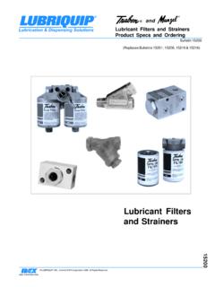
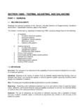
7 Therefore, since internally coupled noise in emission controlled applications can be a source of compromise, Active Filters are best used at frequencies below 100 Hz. Passive Low Pass filter Configurations 3. Figures 3a-c describes the most commonly available (Butterworth type) low pass filter response configurations. For each component added to the filter (inductive or capacitive), the resultant insertion loss is increased by 20 dB per decade in a MIL-STD-220 50 ohm system. However, since real world applications of Filters seldom involve a 50 ohm system, actual insertion loss is Figure 3a Figure 3b Figure 3a-c - Basic Low Pass Butterworth Filters 4. sometimes calculated to determine if the filter selected will have any effect at all on the problem signal. To determine the performance of a manufactured filter relative to an "other then 50 ohm" system, Figure 4 from Murata Erie (1) provides transfer impedance values which can be used to calculate actual responses.
8 The equation for insertion loss (IL) is: Z s Zl . IL ( dB ) = 20 log 1 + . Z 12 ( Z Z ). s l . where Zs is the source impedance Zl is the load impedance Z12 is the transfer impedance Figure 4 - Insertion Loss vs. Transfer Impedance (50 ohm System). The transfer impedance is taken from the graph based on the insertion loss specified for the filter in a 50 ohm system. In addition to impedance matching characteristics, each filter has unique characteristics related to the internal resistance and inductance of its capacitor(s), and the parasitic capacitance of its inductor(s). The "C" feed-through filter of Figure 3a is a low impedance filter very efficient for low voltage applications, and/or when both source and load impedances are high. Attenuation for this type of filter is generally between 20 to 40 dB at medium frequencies of around 150 KHz, reducing its usage in most emission controlled applications.
9 The "Pie section of Figure 3a is a low impedance filter used where both source and load impedances are high. Being the most commonly used filter in all applications, it is also one of the most efficient filter types for meeting any voltage and insertion loss requirement. 5. The "L section (Figure 3a) is used on high impedance noise sources and low impedance lines. It is also sometimes used when an output monitoring line is required for a sensitive signal line located inside the Red section of a box. So far as applications for direct filtering of a signal line is concerned, the filter will resonate when shocked with transient noise at selected frequencies, producing dips in the Filters resonance curve. Therefore, it is seldom used in direct emission controlled emission control applications. The T" section (Figure 3b) is used where both the source and the load impedances are low. The filter is very effective in reducing transient type interference since it eliminates ringing, and is normally recommended for circuit interrupting devices.
10 Table 1 provides the consolidated selection criteria for each filter type. Table 1 I/O Impedance and Selection Criteria High Input/High Output Feed Through Impedance Pie Double Pie High Input/Low Output L (C first). Impedance Double L (C first). Low Input/High Output L (L first). Impedance Double L (L first). Low Input/Low Output Impedance Choke T. Double T. Figure 5 and 6 provide insertion loss characteristics and response equations for typical RC, RL, and LC type circuits. Figure 7 is an example of a series to parallel transformation of an RL. circuit. Since custom made Filters are expensive, most engineers will usually specify available off-the-shelf Filters . Basic Powerline Filters Emission controlled powerline Filters can be used in both box and system level applications. The preferred choice for installation is at the equipment level rather than filtering the source of the power at the first service disconnect such as the condition depicted in Figure 8.