Transcription of Basic Calculation of a Boost Converter's Power Stage (Rev. C)
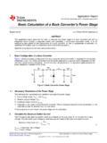
1 VINVOUTIINIOUTCINCOUTLDSWA pplicationReportSLVA372C November2009 RevisedJanuary2014 BasicCalculationof a BoostConverter's PowerDC/DCApplicationABSTRACTThis applicationnotegivesthe equationsto calculatethe powerstageof a boostconverterbuilt with an ICwith integratedswitchand operatingin is not intendedto give detailsonthe functionalityof a boostconverter(seeReference1) or howto compensatea the end of this documentif moredetailis the equationswithoutdescription,See a BoostConverterFigure1 showsthe basicconfigurationof a boostconverterwherethe switchis integratedin the diodereplacedby a secondswitchintegratedinto the is the case,all equationsin this documentapplybesidesthe powerdissipationequationof the the PowerStageThe followingfour parametersare neededto calculatethe powerstage:1. InputVoltageRange:VIN(min)and VIN(max)2. NominalOutputVoltage:VOUT3.
2 MaximumOutputCurrent:IOUT(max)4. IntegratedCircuitusedto buildthe is necessary,becausesomeparametersforthe calculationshaveto be takenout of the theseparametersare knownthe calculationof the powerstagecan take November2009 RevisedJanuary2014 BasicCalculationof a BoostConverter's PowerStageSubmitDocumentationFeedbackCop yright 2009 2014,TexasInstrumentsIncorporatedOUT(max )LSW(max)I!II=+21 D-LMAXOUTLIM(min)!II= I(1 D)2 - - IN(m in)LSVD!I =fL IN(min)OUTV D = 1V -Calculatethe MaximumSwitchCurrentThe first step to calculatethe switchcurrentis to determinethe duty cycle,D, for the minimuminputvoltageis usedbecausethis leadsto the maximumswitchcurrent.(1)VIN(min)= minimuminputvoltageVOUT= desiredoutputvoltage = efficiencyof the converter, estimated80%The efficiencyis addedto the duty cyclecalculation,becausethe converterhas to deliveralso the calculationgivesa morerealisticduty cyclethanjust the equationwithoutthe estimatedfactor, 80%(whichis not unrealisticfor a boostconverterworstcaseefficiency),can be usedor see theTypicalCharacteristicssectionof the selectedconverter'sdatasheet( Reference3 and 4).
3 The next step to calculatethe maximumswitchcurrentis to determinethe theconvertersdatasheetnormallya specificinductoror a rangeof inductorsis namedto use with the IC. Soeitheruse the recommendedinductorvalueto calculatethe ripplecurrent,an inductorvaluein the middleof the recommendedrangeor, if noneis givenin the datasheet,the one calculatedin theInductorSelectionsectionof this applicationnote.(2)VIN(min)= minimuminputvoltageD = duty cyclecalculatedin Equation1fS= minimumswitchingfrequencyof the converterL = selectedinductorvalueNowit has to be determinedif the selectedIC can deliverthe maximumoutputcurrent.(3)ILIM(min)= minimumvalueof the currentlimit of the integratedswitch(givenin the datasheet) IL= inductorripplecurrentcalculatedin Equation2D = duty cyclecalculatedin Equation1If the calculatedvaluefor the maximumoutputcurrentof the selectedIC, IMAXOUT, is belowthe systemsrequiredmaximumoutputcurrent,anot herIC with a higherswitchcurrentlimit has to be the calculatevaluefor IMAXOUTis just a little smallerthanthe neededone,it is possibleto use theselectedIC with an inductorwith higherinductanceif it is still in the higherinductancereducesthe ripplecurrentand thereforeincreasesthe maximumoutputcurrentwith the calculatedvalueis abovethe maximumoutputcurrentof the application,the maximumswitchcurrentin the systemis calculated.
4 (4) IL= inductorripplecurrentcalculatedin Equation2 IOUT(max)= maximumoutputcurrentnecessaryin the applicationD = duty cyclecalculatedin Equation1 This is the peakcurrent,the inductor,the integratedswitch(es)and the externaldiodehas to a BoostConverter's PowerStageSLVA372C November2009 RevisedJanuary2014 SubmitDocumentationFeedbackCopyright 2009 2014,TexasInstrumentsIncorporatedDFFP = IV FO UT (m ax)I = IOUTLOUT(max)INV!I = ( to )IV ()INOUTINLSOUTV VVL =!IfV- a rangeof this is the case,it is recommendedtochoosean inductorfromthis higherthe inductorvalue,the higheris the maximumoutputcurrentbecauseof the lowerthe inductorvalue,the smalleris the the inductormustalwayshaveahighercurrentrati ngthanthe maximumcurrentgivenin Equation4 becausethe partswhereno inductorrangeis given,the followingequationis a goodestimationfor the rightinductor:(5)VIN= typicalinputvoltageVOUT= desiredoutputvoltagefS= minimumswitchingfrequencyof the converter IL= estimatedinductorripplecurrent,see belowThe inductorripplecurrentcannotbe calculatedwith Equation1 becausethe inductoris not the inductorripplecurrentis 20%to 40%of the outputcurrent.
5 (6) IL= estimatedinductorripplecurrentIOUT(max)= maximumoutputcurrentnecessaryin the application4 RectifierDiodeSelectionTo reducelosses,Schottkydiodesshouldbe forwardcurrentratingneededis equalto themaximumoutputcurrent:(7)IF= averageforwardcurrentof the rectifierdiodeIOUT(max)= maximumoutputcurrentnecessaryin the applicationSchottkydiodeshavea higherpeakcurrentin the systemis not a otherparameterthat has to be checkedis the powerdissipationof the has to handle:(8)IF= averageforwardcurrentof the rectifierdiodeVF= forwardvoltageof the rectifierdiode3 SLVA372C November2009 RevisedJanuary2014 BasicCalculationof a BoostConverter's PowerStageSubmitDocumentationFeedbackCop yright 2009 2014,TexasInstrumentsIncorporatedOUT12 FBVR = R1V - FB2R1/2VR =IR1/2 FBI100 I R1R2IR1 convertersset the outputvoltagewith a resistivedividernetwork(whichis integratedif they arefixedoutputvoltageconverters).
6 Withthe givenfeedbackvoltage,VFB, and feedbackbias current,IFB, the voltagedividercan be ResistiveDividerfor Settingthe OutputVoltageThe currentthroughthe resistivedividershallbe at least100 timesas big as the feedbackbias current:(9)IR1/2= currentthroughthe resistivedividerto GNDIFB= feedbackbias currentfromdatasheetThis addsless than1% inaccuracyto the currentcan also be a lot disadvantageof smallerresistorvaluesis a higherpowerloss in the resistivedivider,but theaccuracywill be a little aboveassumption,the resistorsare calculatedas follows:(10)(11)R1,R2= resistivedivider,see feedbackvoltagefromthe datasheetIR1/2= currentthroughthe resistivedividerto GND,calculatedin Equation9 VOUT= desiredoutputvoltage6 InputCapacitorSelectionThe minimumvaluefor the inputcapacitoris normallygivenin the minimumvalueisnecessaryto stabilizethe inputvoltagedue to the peakcurrentrequirementof a best practiceis to use low equivalentseriesresistance(ESR) dielectricmaterialshouldbe X5 Ror ,the capacitorcanelose muchof its capacitancedue to DCbias or temperature(seereferences7 and 8).
7 The valuecan be increasedif the inputvoltageis a BoostConverter's PowerStageSLVA372C November2009 RevisedJanuary2014 SubmitDocumentationFeedbackCopyright 2009 2014,TexasInstrumentsIncorporatedOUT(max )LOUT(ESR)I!I!V= ESR+1 D2 - OUT(max)OUT(min)SOUTIDC=f!V to use low ESRcapacitorsto minimizethe rippleon the a goodchoiceif the dielectricmaterialis X5 Ror better(seereference7 and 8).If the converterhas externalcompensation,any capacitorvalueabovethe recommendedminimumin thedatasheetcan be used,but the compensationhas to be adjustedfor the ,the recommendedinductorand capacitorvaluesshouldbe usedor the recommendationsin the datasheetfor adjustingthe outputcapacitorsto the applicationshouldbefollowedfor the ratioof L ,the followingequationscan be usedto adjustthe outputcapacitorvaluesfora desiredoutputvoltageripple:(12)COUT(min) = minimumoutputcapacitanceIOUT(max)= maximumoutputcurrentof the applicationD = duty cyclecalculatedwith Equation1fS= minimumswitchingfrequencyof the converter VOUT= desiredoutputvoltagerippleThe ESRof the outputcapacitoraddssomemoreripple,givenw ith the equation.
8 (13) VOUT(ESR)= additionaloutputvoltagerippledue to capacitorsESRESR= equivalentseriesresistanceof the usedoutputcapacitorIOUT(max)= maximumoutputcurrentof the applicationD = duty cyclecalculatedwith Equation1 IL= inductorripplecurrentfromEquation2 or Equation65 SLVA372C November2009 RevisedJanuary2014 BasicCalculationof a BoostConverter's PowerStageSubmitDocumentationFeedbackCop yright 2009 2014,TexasInstrumentsIncorporatedFB2R1/2 VValue of Resistor Between FB Pin and GND: R =IR1/2 FBCurrent Through Resistive Divider Newtwork for Output Voltage Setting: I100 I DFFP ower Dissipation in rectifier Diode: P = IV FOUT(max)Average Forward Current of rectifier Diode: I = IOUTLOUT(max)INVI nductor Ripple Current Estimation: !I = ( to )IV ()INOUTINLSOUTV VVInductor Calculation : L =!IfV- OUT(max)LSW(max)I!IApplication specific maximum switch current: I=+21 D-LMAXOUTLIM(min)!
9 IMaximum output current of the selected IC: I= I(1 D)2 - - IN (mi n)LSVDI nductor Ripple Current:!I =fL IN(min)OUTV Maximum Duty Cycle: D = 1V -Equationsto Calculatethe PowerStageof a Calculatethe PowerStageof a BoostConverter(14)VIN(min)= minimuminputvoltageVOUT= desiredoutputvoltage = efficiencyof the converter, estimated85%(15)VIN(min)= minimuminputvoltageD = duty cyclecalculatedin Equation14fS= minimumswitchingfrequencyof the converterL = selectedinductorvalue(16)ILIM(min)= minimumvalueof the currentlimit of the integratedwitch(givenin the datasheet) IL= inductorripplecurrentcalculatedin Equation15D = duty cyclecalculatedin Equation14(17) IL= inductorripplecurrentcalculatedin Equation15 IOUT(max)= maximumoutputcurrentnecessaryin the applicationD = duty cyclecalculatedin Equation14(18)VIN= typicalinputvoltageVOUT= desiredoutputvoltagefS= minimumswitchingfrequencyof the converter IL= estimatedinductorripplecurrent,see Equation19(19)
10 IL= estimatedinductorripplecurrentIOUT(max)= maximumoutputcurrentnecessaryin the application(20)IOUT(max)= maximumoutputcurrentnecessaryin the application(21)IF= averageforwardcurrentof the rectifierdiodeVF= forwardvoltageof the rectifierdiode(22)IFB= feedbackbias currentfromdatasheet(23)6 BasicCalculationof a BoostConverter's PowerStageSLVA372C November2009 RevisedJanuary2014 SubmitDocumentationFeedbackCopyright 2009 2014,TexasInstrumentsIncorporated:OUT(ma x)LOUT(ESR)I!IAdditional Output Voltage Ripple due to ESR !V= ESR+1 D2 - OUT(max)OUT(min)SOUTIDM inimum Output Capacitance, if not given in the data sheet: C=f!V OUTOUT 12 FBVV alue of Resistor Between FB Pin and V : R = R1V - Calculatethe PowerStageof a BoostConverter(24)VFB= feedbackvoltagefromthe datasheetIR1/2= currentthroughthe resistivedividerto GND,calculatedin Equation22 VOUT= desiredoutputvoltage(25)IOUT(max)= maximumoutputcurrentof the applicationD = duty cyclecalculatedin Equation14fS= minimumswitchingfrequencyof the converter VOUT= desiredoutputvoltageripple(26)ESR= equivalentseriesresistanceof the usedoutputcapacitorIOUT(max)= maximumoutputcurrentof the applicationD = duty cyclecalculatedin Equation14 IL= inductorripplecurrentfromEquation15 or Equation197 SLVA372C November2009 RevisedJanuary2014 BasicCalculationof a BoostConverter's PowerStageSubmitDocumentationFeedbackCop yright 2009 2014, SwitchmodePowerSupplies(SLVA061) TPS61030(SLVA274)3.