Transcription of Basic Lift Pump Installation - Kennedy Diesel
1 Basic Lift Pump Installation fuel tank removal is shown for pictorial aid only. Twin pump and single pump Installation is the same as is the Pump filter combo. Installing lift supply pumps on a Duramax is a very straight forward procedure. This guide will cover using Basic supply hose and OE connections. To remove the OE lines you will need the Lisle QD tool (image 1) to disconnect the OE quick connects for both the supply and return. If you plan t drop the tank, removal is pretty Basic , just be sure to disconnect the sending unit electrical plug, the filler neck ground strap, and the filler neck from the body attach at the fuel door.
2 Use a clean rag or towel to plug filler neck while doing this. All plumbing for this Installation is taking the place of the OE supply hose (image 2) and will be easily reversible by re-installing this hose if the need arises. Image 1 Image 2 The LB7 thru LMM use sending unit/pickup assemblies with supply nipples. The LML uses a smaller metric size. I prefer to use a softer hose for these applications and push the hose over the bump ring on the OE connections. We are basically connecting the OE feed nipple (image 3) to the OE steel line (image 4) behind the fuel cooler.
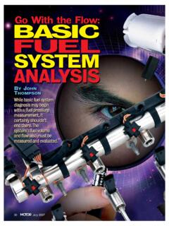
3 The purpose of pushing over the bump ring is to ensure that the hose does not slip off when clamped. The clamp may be placed on or beyond the bulge in the hose. We now include push connect fittings for ease of Installation . This makes does 2 connections out of one, but some prefer the quicker Installation . Note: The LML should not use the push lock at the tank sender as the tank sender outlet nipple is an undersized metric size. Image 3 Image 4 The pumps can be mounted in numerous locations. The preferred method is with our stainless steel mounting bracket as shown in image 5.
4 This is a no drill operation for most models and uses a single bolt through an existing hole in the frame. The pump(s) then bolt directly to the bracket using stainless bolts. For alternative mounting they can be mounted to the tank shield (image 7) the overhead bracket found only on 04+ trucks (image 8) or to the frame rail ahead of the fuel cooler etc. Be sure to mount the pump(s) with the electrical part (motor) face down as shown Image 5 Image 6 Image 7 Image 8 Pump location will dictate hose lengths. Be sure that hoses are routed so as not to kink, cut, or chafe on any component especially the drive shaft and tank shield.
5 Sharp edges on tank shield can be blunted by folding the shield over or by slicing a section of hose and applying it like a door edge molding. Important notes regarding pump operation and warranty please read: It is highly advisable that you verify lift pump operating pressure at the time of install, and again periodically just for good measures. The KD pumps are a centrifugal style which allows them to move a very large volume of fuel at moderate at low pressure. A single pump will deliver about 2-4 psi and twins will produce 6-8 psi. These pumps pose nearly zero restriction in the event of pump stoppage.
6 The magnetic drive design of the motor eliminates any shafts or shaft seals and any worries about leakage into the motor or elsewhere. There is only one simple O-ring seal and that ring is placed under compression rather than sealing a rotating shaft so the result is a leak proof design that will last for many years. Operation of these pumps is nearly silent. pumps may be mounted in most any position other than inverted, but preference is to have the motor hang downward or horizontal. Mounting the motor inverted can allow an air pocket to exist potentially reducing the motor s ability to cool to the fuel .
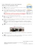
7 Being a centrifugal design, these pumps will NOT prime themselves. When Installation is complete they MUST be bled properly. In most cases I simply start the truck prior to powering the pumps . I have found that the Duramax engine can easily pass the air in the lines and continue to run, pushing the air back to the tank. Once the engine has been run for a few minutes, I recommend a quick drive to be sure to pull any air through the pumps . I then apply the power to the pumps , bleed filter(s), and verify pressure with my KD fuel Filter Restriction/Lift Pump Psi Gauge. This is also a good time to verify restriction with pumps stopped, new filter(s) and a full tank of fuel .
8 Failure to verify proper bleeding can lead to pump failure. Additionally, running out of fuel can cause loss of prime. Recovery is simple as noted above. When in doubt, unplug the pump(s) and drive a bit then re-apply power and verify pressure. Quite simple! Pump/Filter combo notes: The rear pump MUST be bled independently. When properly bled there should be fuel discharge at the filter bleeder any time the pumps are running. If not, there is air in the pump and it must be bled. This can be tricky some times. A sure fire way to bleed this is to apply a small amount of air pressure through the fill neck until fuel discharges from the bleeder.
9 Use caution to only apply a slight amount of pressure so as not to damage the tank, and release it slowly to prevent back flow from the filler.