Transcription of Basic principle and methodology of weld joints …
1 Basic principle and methodology of weld joints design This chapter describes Basic principle and methodology of weld joints design for static and dynamic loading to develop groove and fillet weld joints besides the information required for developing said designs. Keywords: Design of weld joint, static and dynamic loading, load resisting cross sectional area, allowable stress, throat thickness, leg length, class of weld , stress range Design of weld joint for static loading As mentioned in section for designing of a weld joint, it is required to determine the throat thickness and length of the weld .
2 Measurement of throat thickness is easier for groove butt weld joint than fillet weld joint because root is not accessible in case of fillet weld . Throat thickness of fillet welds is obtained indirectly (mathematically) from leg length: 21/2X leg length. Leg length of fillet weld can be measured directly using metrological instruments. Further, for a particular plate thickness, minimum throat thickness values have been fixed by American welding society in view of cracking tendency of fillet weld due to tensile residual stresses in weld joints . Small fillet weld developed on thick plate exhibits cracking tendency appreciably due to inability of small fillet to sustain heavy residual tensile stresses which develop in small fillet weld .
3 It is important to note that depending upon the expected service load, a weld joint can be designed by considering tensile, compressive and shear stresses. A weldment joint design program starts with recognition of a need to design expected to be induced during the service.(new design or failure of existing design ) a weld joints followed by main steps of weldment design procedure including: 1. Determination or estimation of expected service load on the weld joint 2. Collecting information about working condition and type of stresses 3.
4 Based on the requirement identify design criteria (ultimate strength, yield strength, modulus of elasticity) 4. Using suitable design formula calculate length of weld or throat thickness as per need or data given 5. Determine length and throat thickness required to take up given load (tensile, shear bending load etc.) during service methodology Depending upon the service requirements, select the type of weld joint and edge preparation for design Establish the maximum load for which a weld joint is to be designed For a given thickness of the plate usually throat thickness is generally fixed.
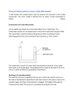
5 For full penetration fillet weld , throat thickness is about time of leg length of the weld and that of groove weld generally is equal to thickness of thinner plate (in case of dissimilar thickness weld ) or thickness of any plate (Fig. ). Using suitable factor of safety and suitable design criteria determine the allowable stress for the weld joint. Subsequently calculate length of the weld using external maximum load, allowable stress, throat thickness and allowable stress. Design of fillet welds (a) Stress on fillet weld joint can be obtained by using following relationship: Load/ weld throat cross sectional area Load/(throat thickness X length of weld joint X number of welds) X leg length of the weld X length of the weld X number of welds Length of weld Leg length of weld Fig.
6 DStress onrelationsweld joinwelds Fig. Stress ( external Schematic and c) throatDesign of bun butt weld jhip: Stress: nt X number Schematic ) on the butload (P) exp b) diagram sh thickness foutt weld joinjoint betwee Load / weldr of welds)=Ldiagram of btt weld joint bperiences echowing a) leor convex fillnt en equal thicd throat crosLoad/ thicknbutt weld bebetween placcentricity (e a) eg length anlet welds ckness platess sectional ness of any tween platesates of differee) owing to c) d length of es (Fig. Load/plate X lengs of equal thent thicknesdifference inweld, b) thr2) is obtaine/(throat thickgth of the whickness ses (T1 andn thickness roat thicknesd using follokness X lengweld X numbd T2) subjectof plates an ss for owing gth of ber of ted to nd T1 thickness of thinner plate of the joint (Fig.
7 Even axial loading due to eccentricity causes the bending stress in addition to axial stress. Therefore, stress on the weld joint becomes sum of axial as well as bending stress and can be calculated as under. Stress in weld = Axial Stress + Bending Stress ePP Fig. Schematic diagram of butt weld when both the plates are of different thickness Design of weld joints for fatigue loading The approach for designing weld joints for fatigue load conditions is different from that of static loading primarily due to high tendency of the fracture by crack nucleation and growth phenomenon.
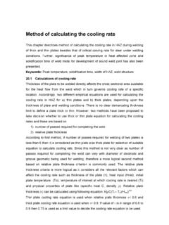
8 A weld joint can be categorized in a specific class depending upon the severity of stress concentration, weld penetration (full or partial penetration weld ), location of weld , type of weld and weld constraint. The class of a weld joint to be designed for fatigue loading is used to identify allowable stress range for a given life of weld joint (number of fatigue load cycles) from stress range vs. number of load cycle curves developed for different loading conditions and metal system (Fig. ). Thus, allowable stress range obtained on the basis of the class of the weld and fatigue life of weld (for which it is to be designed) is used to determine the weld -throat-load-resisting cross-sectional area (throat thickness, length of weld and number of weld ).
9 Fig. joi Idp Fu TmwSt S-N curvesure of weldnts for fatigdentify the enetration For identifiesing fatigueThe allowaminimum loaweld joint ( ) Tens for differentd joint desgue loadingclass of thand criticald class of te life (numbble stress ad) are useFig. ) Tension t classes of ign for fati condition ahe weld joiity of the jothe weld jober of cyclerange aned to deteraverage weld joints (igue loadinare designent based ooint for the sint, obtain aes) for whichnd service rmine load Stressma (Madox, S Kng ed using folon severitysuccess of a value of th it is to be loading cresisting ) 0 TensK, 1991) llowing stepy of loadingthe assembthe allowabdesigned.
10 Condition (cross sectioTimeaveragesion ps: g, type of wbly ble stress ra(maximum onal area oe weld , ange and of the c) Compression Tension d) Fluctuating stress Fig. Common fatigue load patterns For given set of loading condition and identified class of the weld joint various details like throat thickness, length of weld joint and number of welds can be obtained from calculated load resisting cross sectional area desired. Generally, the maximum length of the weld becomes same as the length of the plate to be welded and maximum number of welds for butt welding is one and that for fillet weld can be two for uninterrupted welds.