Transcription of Basic RTD Measurements Basics of Resistance Temperature ...
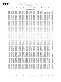
1 Basic RTD Measurements Basics of Resistance Temperature detectors platinum RTD resistances range from about 10 O for a birdcage configuration to 10k O for a film type, but the most common is 100 O at 0 C. Commercial platinum wire has a standard Temperature coefficient, called alpha, of O/O/ C, and chemically pure platinum has a coefficient of O/O/ C. A nominal 100-O platinum wire at 0 C will change Resistance , either plus or minus, over a slope of O/C. For example, a 10 C rise in Temperature will change the output of the sensor from 100 O to O, and a 10 C fall in Temperature will change the RTD Resistance to O. Because RTD sensor resistances and Temperature coefficients are relatively small, lead wires with a total Resistance as low as 10 O and relatively high Temperature coefficients can change the data acquisition system s calibration.
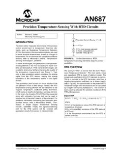
2 The lead wire s Resistance change over Temperature can add to or subtract from the RTD sensor s output and produce appreciable errors in Temperature measurement . The Resistance of the RTD (or any resistor) is determined by passing a measured current through it from a known voltage source. The Resistance is then calculated using Ohms Law. To eliminate the measurement error contributed by lead wires, a second set of voltage sensing leads should be connected to the sensor s terminals and the opposite ends connected to corresponding sense terminals at the signal conditioner. This is called a four-wire RTD measurement . The sensor voltage is measured directly and eliminates the voltage drop in the current carrying leads. For a Basic four-wire measurement method using a current source the RTD Resistance is V/I. This connection is more accurate than the two-wire method, but it requires a high stability current source and four lead wires.
3 Because the high impedance voltmeter does not draw appreciable current, the voltage across the RTD equals Vm. Equation 1: Four-Wire RTD With Current Source Rrtd = Vm Irtd Where: Rrtd = RTD Resistance , O Vm = Voltmeter reading, V Irtd = RTD current, A A three-wire RTD measurement technique using a current source has the RTD Resistance derived from Kirchhoff s voltage law and the solution of two simultaneous equations. (Illustrating the solution is beyond the scope of this TechTip.) The benefit of this connection over the 4 wire RTD is one less lead wire. However, this connection assumes that the two current-carrying wires have the same Resistance . Equation 2: Three-Wire RTD With Current Source Rrtd = Va Vb Irtd With a four-wire measurement system using a voltage source the RTD Resistance also is derived from Kirchhoff s voltage law and four simultaneous equations based on the four voltages.
4 The voltage source in this circuit can vary somewhat as long as the sense resistor remains stable. Equation 3: Four-Wire RTD With Voltage Source Rrtd = Rs (Vb Vc) Vd With a three-wire measurement technique using a voltage source the RTD Resistance is derived from Kirchhoff s voltage law and three simultaneous equations. The voltage source can vary as long as the sense resistor remains stable, and the circuit is accurate as long as the resistances of the two current-carrying wires are the same. Equation 4: Three-Wire RTD With Voltage Source Rrtd = Rs (2Vb Va Vd) Vd The RTD output is more linear than the thermocouple, but its range is smaller. The Callendar-Van Dusen equation, is often used to calculate the RTD Resistance , but it can be cumbersome to use. An alternative method involves measuring RTD resistances at four temperatures and solving a 20th order polynomial equation with these values.
5 It provides more precise data than does the alpha, sigma, and beta coefficients in the Callendar-Van Dusen equation. The plot of the polynomial equation shows the RTD to be more linear than the thermocouple when used below 800 C, the maximum Temperature for RTDs. Self-Heating Another source of error in RTD Measurements is resistive heating. The current, I, passing through the RTD sensor, R, dissipates power, P, where P = I2R. For example, 1 mA through a 100-O RTD generates 100 W. This may seem insignificant, but it can raise the Temperature of some RTDs a significant fraction of a degree. A typical RTD can change 1 C/mW by self-heating. When selecting smaller RTDs for faster response times, consider that they also can have larger self-heating errors. A typical value for self-heating error is 1 C/mW in free air. An RTD immersed in a thermally conductive medium distributes this heat to the medium and the resulting error is smaller.
6 The same RTD rises C/mW in air flowing at 1 m/s. Using the minimum excitation current that provides the desired resolution, and using the largest physically practical RTD will help reduce self-heating errors. Scanning Inputs Since lower currents generate less heat, currents between 100 and 500 A are typically used. This lowers the power dissipation to 10 to 25 W, which most applications can tolerate. Further reducing the current lowers accuracy because they become more susceptible to noise and are more difficult to measure. But switching the current on only when the measurement is made can reduce the RTD s heat to below 10 W. In a multichannel system, for example, the excitation current can be multiplexed, much like the analog inputs. In a 16-channel system, the current will only excite each RTD 1/16th of the time, reducing the power delivered to each RTD from 100% to only 6%.
7 Two practical methods for scanning an RTD include constant current and ratiometric. An constant current circuit is an RTD scanning module, which switches a single 500 A constant current source among 16 channels. A series of front-end multiplexers direct the current to each channel sequentially while the measurement is being taken. Both three and four-wire connections are supported to accommodate both types of RTDs. By applying current to one RTD at a time, errors due to resistive heating become negligible. Advantages of the constant current method include simple circuits and noise immunity. But the disadvantage is the high cost of buying or building an extremely stable constant current source. By contrast, the ratiometric method uses a constant voltage source to provide a current, through the RTD and a resistor. Four voltage readings are taken for each RTD channel.
8 The current, voltage, and Resistance of the RTD is: Equation 5: Four-Wire RTD Ratiometric measurement Is = Vd Rd Vrtd = Vb Vc Rrtd = Vrtd Is For a three-wire connection, the voltage, includes the voltage drop across only one lead. Because the two extension wires to the transducer are made of the same metal, assume that the drop in the first wire is equal to the drop in the second wire. Therefore, the voltage across the RTD and its Resistance is: Equation 6: Three-Wire RTD Ratiometric measurement Rrtd = Rd Vrtd = Va 2(Va Vb) Vd (Vrtd) Practical Precautions RTDs require the same precautions that apply to thermocouples, including using shields and twisted-pair wire, proper sheathing, avoiding stress and steep gradients, and using large diameter extension wire. In addition, the RTD is more fragile than the thermocouple and needs to be protected during use.
9 Also, thermal shunting is a bigger concern for RTDs than for thermocouples because the mass of the RTD is generally much larger. Basics of Thermistors Thermistors are generally composed of semiconductor materials or oxides of common elements such as cobalt, copper, iron, manganese, magnesium, nickel, and others. They typically come with 3 to 6-in. leads, encapsulated, and color-coded. They are available in a range of accuracies from 15 C to 1 C, with a nominal Resistance ranging from 2,000 O to 10,000 O at 25 C. A value of 2252 O is common and can be used with most instruments. A plot of the Temperature vs. Resistance characteristic curves is usually provided with the device to determine the Temperature from a known Resistance . However, the devices are highly non-linear and the following equation may be used to calculate the Temperature : Equation 7: Thermistor Temperature 1 = A + B(logeR) + C(logeR)3 T Where: T = Temperature , K A, B, and C = fitting constants R = Resistance , O The constants A, B, and C are calculated from three simultaneous equations with known data sets: Insert R1 and T1; R2 and T2; R3 and T3, then solve for A, B, and C.
10 Interpolation yields a solution accurate to +/- C or better. (Illustrating the procedure is beyond the scope of this TechTip.) Linearization Some thermistor manufacturers supply devices that provide a near-linear output. They use multiple thermistors (positive and negative coefficients) or a combination of thermistors and metal film resistors in a single package. When connected in certain networks, they produce a linearly varying voltage or Resistance proportional to Temperature . A widely used equation for the voltage divider=: Equation 8: Thermistor Voltage Divider Eout = Ein ( R ) (R + Ro) Where: Eout is the voltage drop across R If R is a thermistor, and the output voltage is plotted against the Temperature , the curve resembles an S-shape with a fairly straight center portion. However, adding other resistors or thermistors to R linearizes the center portion of the curve over a wider Temperature range.