Transcription of Basic Switches BZ - State Elect
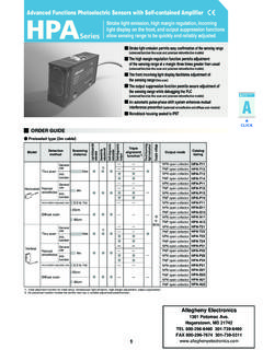
1 1 CLICKCLICKCLICKC lassificationStandard typeLow current load typeActuatorsPin plungerShort plungerPanel mount plungerPanel mount roller plunger/cross roller plungerFine plungerLeverRoller leverShort roller leverOne-way roller leverReverse action leverReverse action roller leverReverse action short roller leverSELECTION GUIDEB asic SwitchesBZSeriesThese Switches have been used extensively and have earned the high respect of our customers. Standard Basic Switches BZ Series are representative of Yamatake Basic Switches for their range of models and high not usea lock washerInsulatorMounting plateInsulatorMounting plateLock washerHolding plateBASIC TYPE COMPLIANT WITE EN (IEC) STANDARDSSWITCH MOUNTING METHODCONTACT & TERMINAL TYPERATING/TERMINAL TYPEItemElectrical ratingCatalog listingScrew terminal10 ABZ-2 RMethod for mountingon a thin plateMethod for mountingon a thick plateMounting screwPanel mount plungerPanel mount roller plungerItemCircuit configurationTypeStandardTypeSingle-Pole Double-Throw (SPDT)BZ-2 RCONTACT SPACING(Example)
2 BZ-2R-T4-JCodeContact model, high accuracy, and long lifeCatalog listing When mounting on a panel, limit the tightening torque of the hexagon head nut on the actuator to When mounting the panel mount plunger/roller plunger on the side panel, the switch is sometimes damaged if the dog startup angle or operation speed is too large. Note that switch is sometimes damaged also if there is too much impact or movement after operation. Drill the mounting holes as follows: EN (IEC) compliant standard type BZ models are available. For details, see page F-006. In catalog listings for Basic Switches , the following code indicates the contact spacingPanel mounting (catalog listing BZ-2RQ - -J) diaWhen mounting by the side screwsBZ Use M4 torque must be to GUIDE ActuatorsStandardscertificationCatalog listingTerminalPin plungerShort plunger Fine plungerLeverRoller leverShort roller (N)Operating (mm)Free (mm)Pretravel (mm)Operating (mm) (mm)Movement (N)Release forcePanel mountplungerPanel mount roller/Cross roller plungerMax.
3 4 Min. screwM4 screwM4 screwM4 screwM4 screwM4 screwM4 screwM4 screwBZ-2R-T4-JBZ-2RD-T4-JBZ-2RQ1-T4-JBZ -2RS-T4-JBZ-2RW80-T4-JBZ-2RW82-T4-JBZ-2R W822-T4-JBZ-2RQ18-T4-J(roller)BZ-2RQ181- T4-J(cross roller)General-purpose Basic Switches : BZ SeriesHigh-quality Switches with UL/CSA certification.*UL approval number: E37559. CSA: LR61643 Wide range of typesStandard typeReverse action lever type (effective when there is impact operation)A wide range of actuators is available. Select the actuator according to your specific requirements and conditions of life: 20 million cycles (pin plunger type)EN 60947-5-1 (IEC 947-5-1) and CCC compliant types are tools and various industrial machineryControl of pressure, temperature, fluid level, weight, speed and timeHousehold equipment, automobiles and control equipmentStandard type4 External DimensionsCircuit configurationTerminal dimensionsScrew terminalBZ-2R-T4-JBZ-2RD-T4-JModelSwitch mountingscrewBZ-2 RSingle-pole double-throw(SPDT)Note: On reverse action types, the and terminal positions are reversed.
4 Reverse actionleverReverse action shortroller leverOne-wayroller leverReverse actionroller leverMax. 1 Min. 2 Min. 4 Min. screwM4 screwM4 screwM4 screwBZ-2RW826-T4-JBZ-2RM-T4-JBZ-2RM2-T4 -JBZ-2RM22-T4-JM4 screwGeneral tolerance: : mm ActuatorsPropertyStandardscertificationC atalog (N)Operating (mm)Free (mm)Pretravel (mm)Operating (mm) (mm) Movement (N)Release forceCircuit configuration and terminal diagrams5BZ-2RQ1-T4-JBZ-2RQ18-T4-JBZ-2RQ 181-T4-JBZ-2RS-T4-JBZ-2RW80-T4-JBZ-2RW82 -T4-JBZ-2RW826-T4-JBZ-2RW822-T4-JGeneral tolerance: : mm6BZ-2RM2-T4-JBZ-2RM-T4-JBZ-2RM22-T4-JC ERTIFIED EN (IEC) COMPLIANT BZ MODELSS tandards: EN 60947-5-1 (IEC 947-5-1)Short rollerleverOne-wayroller leverPanel mountplungerPanel mountroller plungerPanel mountcross roller plungerBZ-2RW3003-T4-JBZ-2RW3003-T4-JKBZ -2RW3005-T4-JBZ-2RQ3000-T4-JBZ-2RQ3000-T 4-JKBZ-2RQ3001-T4-JBZ-2RQ3001-T4-JKBZ-2R Q3002-T4-JBZ-2RQ3002-T4-JKEN compliant standard products are listingNormal loadLow current loadPin plungerShort plungerFine plungerLeverRoller leverBZ-2R3000-T4-JBZ-2R3000-T4-JKBZ-2RD 3000-T4-JBZ-2RD3000-T4-JKBZ-2RS3000-T4-J BZ-2RS3000-T4-JKBZ-2RW3000-T4-JBZ-2RW300 0-T4-JKBZ-2RW3001-T4-JBZ-2RW3001-T4-JKAc tuatorName/ShapeContactCatalog listingNormal loadLow current loadActuatorName/ShapeContactBZ Series Basic switchesNote: Electrical rating for EN (IEC) compliant Switches BZ-2R Standard load: 250 Vac-3A, 30 Vdc-1A Low current load: , : Approving bodys T V Rheinland, Approval No.
5 R9551070 Note: UL/CSA certification also acquiredNote: For details of operation specifications, refer to the same actuator under BZ general purpose : CCC compliant model also available250 Vac or 30 Vdc125 Vac or 30 VdcAC-15 3A-250 Vac, DC-12 1A-30 VdcAC-12 , DC-12 to 65Hz or 250 Vac4,000V15A1 AInstant blowing fuse 15A, ABC 15(15A) made by Bussmann or equivalent1000A-,L,M,N,W,S,Q: Category III D,B: Class loadLow current loadStandard loadLow current loadStandard loadLow current loadRated operatingvoltageApplicationcategory and ratingRated frequencyRated insulating voltage (Ui)Rated impulse dielectric strength (Uimp)Rated energizingcurrent (Ith)Short-circuit protection mechanismConditional rated short-circuit currentSwitching overvoltageElectrical protectionStandard low current load BZ Switches are produced regularly. For details on other types, contact your Yamatake CURRENT LOAD TYPE (cross point contacts)Gold alloy cross point contactNote: Low current load models end in -JK, with K appended to -J at the end of the model (mm)Movement differentialTerminalStandard (mm) (mm)Operating (mm) (mm)Free (N)Release (N)Operating forceCharacteristics are the same as for general purpose standard type.
6 Refer to the page and terminal equipmentAutomatic vendorsNC machine toolsSwitching of miniature loads such as transistors and ICsFeaturesWith cross point contacts, contact is concentrated at one location to enable reliable contact alloy contacts are used for stable contact resistance at all Switches are ideal when minor changes in contact resistance are a problem, for example when switching low current view of contact areaSpecifications8 TypeStandardLow current loadRepresentative catalog listingBZ-2R-T4-JBZ-2R-T4-JKExternalstan dardsComplianceCertificationContact typeContact shapeContact materialTerminal typeInsulation resistanceInitial contact resistanceTemperature riseInrush currentActuator strengthTerminal strengthImpact resistance**Vibration resistance**Allowable operating speedOperating cycleMechanicalElectricalOperating temperatureOperating humidityRecommended torqueInsulationJIS C 4505UL/CSA StructureRivetCross pointSilver alloyGold alloyM4 screw terminalElectrical ratingSee Tables and ,000 VRefer to respective ,000V1,250V2,000V1,250 VMin.
7 100MW(by a 500 Vdc megger)50mW30 C50 C MechanicalcharacteristicsWithstands load 10 times (operating direction) for 1 minuteRefer to respective 20 million cycles, operating frequency 60 cycles/min*250 Vac-15A resistive load, min. 500,000 cyclesEnvironmentalcharacteristicsMax. 85% RHMountingUse an isolator when mounting.* Value for the specified representative catalog listing. Unmarked values are common to models in the series.** contact misoperation in the free position and final overtravel position is 1 ms or current load BZRatingRatingAC ratingDC ratingRated voltage125 Vac250 Vac480 Vac8 Vdc14 Vdc30 Vdc125 Vdc250 VdcSwitching loadResistanceInductionElectric motorResistanceInductionElectric motorResistanceInductionResistanceInduct ionResistanceInductionResistanceInductio nResistanceInductionResistanceInductionE lectric double-throw (SPDT) :AC 250V-30A, :AC 250V-15AM4 screw terminal: Withstands torque for 1 minuteM3 screw terminal: Withstands torque for 1 minute300m/s2* to *Max.
8 240 cycles/minMin. resistive load, 20 million cycles-20 to +70 to (M4 screw) peak-to-peak amplitude, frequency 10 to 55Hz, for 2 continuous hours* , rating,125, 250, 480 Vac-10A,1/8HP-125 Vac,1/4HP-250 Vac,125 Vdc-1/2A250 Vdc-1/4 ASPECIFICATIONSD ielectric strengthBetween non-continuous terminalsBetween each terminal and non-live metal partBetween each terminal and ground Table BZ. 1 Electrical ratingTable BZ. 2 Electric duty 1BZ-2R95PA2-JFor screw terminalPRECAUTIONS FOR USE OF BZ protection the actual the switchWe recommend combined use of a spring washer and adhesive lock to prevent the screw from coming sure that sufficient insulating space is maintained between terminals and ground when the switch is that no force is applied to the actuator when it should be in a free State , and that force is applied along the axis of actuator motion Set function after operating to at least 70% of the rated as the standard mounting a lever type switch, do not apply unnecessary force from the direction opposite to the operating direction or from the using round or open tip (Y-shaped)
9 Crimped terminals with a torque of or the switch taking into consideration that the switch should not malfunction even if the operating characteristics change by 20% of the rated use at dusty locations or at locations subject to corrosive gases or silicon that may adversely influence the using the switch for switching inductive loads (relays, s o l e n o i d s , b u z z e r s , e t c . ) , a r c m a y c a u s e t h e c o n t a c t s t o m a l f u n c t i o n . T o p r e v e n t t h i s , w e r e c o m m e n d i n s e r t i n g a n adequate spark eliminating may drop if synchronization occurs in the AC improve reliability during actual use, we request that you check the quality of the switch in an actual operating State . Because this cover is secured with the switch mounting screws, handling is easy and accidental contact with exposed terminals is prevented.