Transcription of Basic Verilog - University of Massachusetts Amherst
1 1 Part 3: Verilog : Hardware Organization and DesignECE 232 Verilog tutorial2 Basic Verilogmodule <module_name> (<module_terminal_list>); <module_terminal_definitions>..<functionality_of_module>..endmoduleEngin 112 Verilog examples: 353 Verilog Resources 667 Verilog (on the left side menu): 232 Verilog tutorial3 Full Addermodule FullAdder(a,b,cin,cout,sum);input a, b, cin; // inputsoutput cout, sum; // outputwire w1, w2, w3, w4; // internal netsxor#(10) (w1, a, b); // delay time of 10 unitsxor#(10) (sum, w1, cin); and #(8) (w2, a, b);and #(8) (w3, a, cin);and #(8) (w4, b, cin);or #(10, 8)(cout, w2, w3, w4); // (rise time of 10, fall 8)endmoduleabcincoutsum ECE 232 Verilog tutorial4 Multiple ways of implementing Full Addermodule FullAdder(a,b,cin,sum,cout);input a,b,cin; output sum, cout; reg sum, cout; // registers retain valuealways @ (a or b or cin) // Anytime a or b or cinCHANGE, run the process begin sum <= a ^ b ^ cin.
2 Cout <= (a & b) | (a & cin) | (b end endmoduleconcurrent assignment blocking assignment, non-blocking assignments3 ECE 232 Verilog tutorial5 Ripple Carry Adder4-bit Addermodule adder4(A, B, cin, S, cout);input[3:0] A, B;input cin;output[3:0] S;output cout;wire c1, c2, c3;// 4 instantiated 1-bit Full AddersFullAdder fa0(A[0], B[0], cin, c1, S[0]);FullAdder fa1(A[1], B[1], c1, c2, S[1]);FullAdder fa2(A[2], B[2], c2, c3, S[2]);FullAdder fa3(A[3], B[3], c3, cout, S[3]);endmoduleECE 232 Verilog tutorial6 HDL Overview Hardware description languages (HDL) offer a way to design circuits using text-based descriptions HDL describes hardware using keywords and expressions. Representations for common forms Logic expressions, truth tables, functions, logic gates Any combinational or sequential circuit HDLs have two objectives Allow for testing/verificationusing computer simulation Includes syntax for timing , delays Allow for synthesis Synthesizable HDL The two forms often differ !)
3 We will use synthesizable subsetof Verilog Two primary hardware description languages vhdl Verilog4 ECE 232 Verilog tutorial7 Hardware Description Language - Verilog Represents hardware structure and behavior Logic simulation : generates waveforms//HDL Example 1//--------------------------modulesmpl_ circuit(A,B,C,x,y);input A,B,C;outputx,y;wiree;andg1(e,A,B);notg2 (y,C);org3(x,e,y);endmodule Detect errors before fabricationECE 232 Verilog tutorial8 Lines that begin with // are comments (ignored by simulation ) About 100 keywords in total (keywords are case sensitive) module: Building block in Verilog Always terminates with endmodule modulefollowed by circuit name and port list Each port is either an inputor output//HDL Example 2//--------------------------modulesmpl_ circuit(A,B,C,x,y);inputA,B,C;outputx,y; wiree;andg1(e,A,B);notg2(y,C);org3(x,e,y );endmoduleVerilog Keywords and Syntax5 ECE 232 Verilog tutorial9 Verilog StatementsVerilog has two Basic types of statements (combinational)(things are happening concurrently, ordering does not matter) Gate instantiationsand(z, x, y), or(c, a, b), xor(S, x, y), etc.
4 Continuous assignmentsassignZ = x c = a | b; S = x ^ y statements (sequential)(executed in the order written in the code) always @- executed continuously when the event is activealways @(posedgeclock) initial- executed only once (used in simulation ) if then elsestatementsECE 232 Verilog tutorial10wireandgate-levelKeywords wiredefines internal circuit connection Each gate (and, or, not) defined on a separate line Gate I/O includes wires and port values Note: each gate is instantiatedwith a name ( , g1)//HDL Example 2//--------------------------modulesmpl_ circuit(A,B,C,x,y);inputA,B,C;outputx,y; wiree;andg1(e,A,B);notg2(y,C);org3(x,e,y );endmodule Example of gate instantiation6 ECE 232 Verilog tutorial11 Specifying Boolean Expressions assignkeyword used to indicate expression Assignment takes place continuously Note new symbols specific for Verilog OR -> | AND -> & NOT -> ~//HDL Example 3//------------------------------//Circu it specified with Boolean equationsmodule circuit_bln (x,y,A,B,C,D);input A,B,C,D;output x,y;assign x = A | (B & C) | (~B assign y = (~B & C) | (B & ~C endmodule Example of continuous assignmentECE 232 Verilog tutorial12 User Defined Primitives Allows definition of truth table Only one output is allowed//HDL Example 4//-----------------------------------// User defined primitive(UDP) primitive crctp (x,A,B,C);output x;input A,B,C;//Truth table for x(A,B,C) = Minterms (0,2,4,6,7)table// A B C : x (Note that this is only a comment)0 0 0 : 1;0 0 1 : 0;0 1 0 : 1;0 1 1 : 0;1 0 0 : 1.))
5 1 0 1 : 0;1 1 0 : 1;1 1 1 : 1;endtableendprimitive7 ECE 232 Verilog tutorial13 More Verilog Examples - 1 Combinational functionality All assignments take place at the same time Note declaration of a bus output [0:3] D;//HDL Example 5//------------------------------------- ---------//Dataflow description of a 2-to-4-line decoder module decoder_df (A,B,E,D);input A,B,E;output [0:3] D;assign D[0] = ~(~A & ~B & ~E),D[1] = ~(~A & B & ~E),D[2] = ~(A & ~B & ~E),D[3] = ~(A endmoduleECE 232 Verilog tutorial14 More Verilog Examples - 2 Easy to define arithmetic functionality Each comparison creates a single bit result Synthesizer automatically converts RTL description to gate-level description RTL = register transfer level//HDL Example 6//-----------------------------------// Dataflow description of a 4-bit mag_comp (A,B,ALTB,AGTB,AEQB);input [3:0] A,B;output ALTB,AGTB,AEQB;assign ALTB = (A < B),AGTB = (A > B),AEQB = (A == B);endmodule8 ECE 232 Verilog tutorial15 More Verilog Examples - 3 Conditional statements (if, else) allow for output choices always keyword used to indicate action based on variable change Generally conditional statements lead to multiplexers//HDL Example 7//---------------------------------//Be havioral description of 2-to-1-line multiplexermodule mux2x1_bh(A,B,select,OUT);input A,B,select;output OUT;reg OUT; always @ (select or A or B) if (select == 1) OUT = A;else OUT = B.)
6 Endmodule Example of sequential assignmentECE 232 Verilog tutorial16 Modeling Circuit Delay This is for simulation only (not for synthesis) Timescale directive indicates units of time for simulation timescale 1ns / 100ps #(30) indicates an input to output delay for gate g1of 30 ns #(10)indicates an input to output delay for gate g2of 10 ns//HDL Example 2//---------------------------------//De scription of circuit with delay module circuit_with_delay (A,B,C,x,y);input A,B,C;output x,y;wire e;and #(30) g1(e,A,B);or #(20) g3(x,e,y);not #(10) g2(y,C);endmodule9 ECE 232 Verilog tutorial17//HDL Example 8 //Stimulus for simple circuitmodule stimcrct;reg A,B,C;wire x,y;circuit_with_delay cwd(A,B,C,x,y);initialbeginA = 1'b0; B = 1'b0; C = 1'b0;#100A = 1'b1; B = 1'b1; C = 1'b1;#100 $finish; endendmodule//Description of circuit with delay // NOT synthesizable !module circuit_with_delay (A,B,C,x,y);input A,B,C;output x,y;wire e;and #(30) g1(e,A,B);or #(20) g3(x,e,y);not #(10) g2(y,C);endmodule Module circuit_with_delay is instantiated regkeyword indicates that values are stored (driven) Stimulus signals are applied sequentially $finishindicates simulation should end Result: collection of waveformsTest bench Stimulus - 1 ECE 232 Verilog tutorial18 Test bench Stimulus - 2 Timescale directive indicates units of time for simulation timescale 1ns / 100ps Note that input values change at 100ns Shaded area at left indicates output values are undefined10 ECE 232 Verilog tutorial19Q$latchDENAPRECLRQDClkQModelin g Sequential ElementsmoduleD-latch (D, Clk, Q);inputD, Clk;output Q;regQ;always @(D orClk)if(Clk)Q = D;endmoduleD LatchECE 232 Verilog tutorial20 Verilog D Flip-flopmoduleD-flipflop (D, Clk, Q);inputD, Clk;output Q;regQ.
7 Always @(posedgeClk)Q = D;endmoduleQ~reg0 DENAQPRECLRDClkQ11 ECE 232 Verilog tutorial21Q2~reg0 DENAQPRECLRQ1~reg0 DENAQPRECLRDC lockQ1Q2 Verilog - Blocking Assignment (=)moduleDFF-blocking(D, Clock, Q1, Q2);inputD, Clock;output Q1, Q2;regQ1, Q2;always @(posedge Clock)begin// blocking assignment series executionQ1 =D;Q2 =Q1;endendmoduleECE 232 Verilog tutorial22Q2~reg0 DENAQPRECLRQ1~reg0 DENAQPRECLRDC lockQ1Q2 Verilog Non-blocking Assignment (<=)moduleDFF-non-blocking(D, Clock, Q1, Q2);inputD, Clock;output Q1, Q2;regQ1, Q2;always @(posedgeClock)begin// non blocking assignment - can be done in parallel (or any order)Q1 <=D;Q2 <=Q1;endendmodule12 ECE 232 Verilog tutorial23Q~reg0 DENAQPRECLRDC lockResetnQVerilog D Flip-flop with Resetmoduledff_reset(D, Clock, Resetn, Q);inputD, Clock, Resetn;outputQ;regQ;always @(negedgeResetn or posedgeClock)if(!Resetn)Q <=0;elseQ <=D;endmodule D flip-flop with asynchronousreset (asserted negative)ECE 232 Verilog tutorial24 Mealy FSM Output based on present state and input Output changes during transitionS1S2in/outS2/out2inS1/out1 Moore FSM Output based on state only Output is associated with stateFinite State Machines - 113 ECE 232 Verilog tutorial25 Finite State Machines - 2 State diagrams are representations of Finite State Machines(FSM) Mealy FSM Output depends on inputand state Output is not synchronized with clock can have temporarily unstable output Moore FSM Output depends only on stateMealy FSMM oore FSMECE 232 Verilog tutorial26 Example 1: Sequence Detector Circuit specification: Design a circuit that outputs a 1 when three consecutive 1 s have been received as input and 0 otherwise.
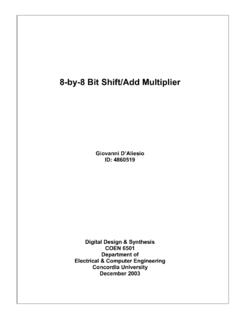
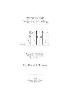
8 FSM type Moore or Mealy FSM? Both possible Chose Moore to simplify diagram State diagram: State S0: zero 1s detected State S1: one 1 detected State S2: two 1s detected State S3: three 1s detected14 ECE 232 Verilog tutorial27 Sequence Detector: Verilog (Moore FSM)moduleseq3_detect_moore(x,clk, y);// Moore machine for a three-1s sequence detectioninputx, clk;outputy;reg[1:0] state;parameterS0=2'b00, S1=2'b01, S2=2'b10, S3=2'b11;// Define the sequential blockalways @(posedgeclk)case(state)S0: if(x) state <= S1;elsestate <= S0;S1: if(x) state <= S2;elsestate <= S0;S2: if(x) state <= S3;elsestate <= S0;S3: if (x) state <= S3;elsestate <= S0;endcase// Define output during S3assigny = (state == S3);endmoduleECE 232 Verilog tutorial28 Sequence Detector:FSM Synthesis + simulation Synthesized Moore FSM (Quartus) simulation results (Quartus)S0S1S2S3reset15 ECE 232 Verilog tutorial29 Sequence Detector: Verilog (Mealy FSM)moduleseq3_detect_mealy(x,clk, y);// Mealy machine for a three-1s sequence detectioninputx, clk;outputy;regy;reg[1:0] pstate, nstate; //present and next statesparameterS0=2'b00, S1=2'b01, S2=2'b10, S3=2'b11;// Next state and output combinational logic// Use blocking assignments "="always @(x orpstate)case(pstate)S0: if(x) beginnstate = S1; y = 0; endelsebegin nstate = S0; y = 0; endS1: if (x)beginnstate = S2; y = 0; end elsebegin nstate = S0; y = 0; endS2: if (x)beginnstate = S3; y = 0; endelsebegin nstate = S0; y = 0; endS3: if(x)beginnstate = S3; y = 1; endelse beginnstate = S0; y = 0; endendcase// Sequential logic, use nonblocking assignments "<="always @(posedgeclk)pstate <= nstate.
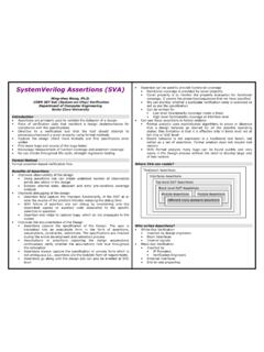
9 EndmoduleS0S1S2S30/01/01/00/00/01/11/00/ 0 ECE 232 Verilog tutorial30 Sequence Detector: FSM Synthesis + simulation Synthesized Mealy FSM (Quartus) simulation results (Quartus)pstate:S3y~0xxclkpstatexclkS3y~ 0010xclky16 ECE 232 Verilog tutorial31 Example 2: Vending Machine FSM - 1 Specify the Problem Deliver package of gum after 15 cents deposited Single coin slot for dimes, nickels No change Design the FSM using combinational logic and flip flopsVending Machine FSMNDR esetClkOpenCoin SensorGum Release MechanismECE 232 Verilog tutorial32 Example 2: Vending Machine FSM - 2 ResetNNN, D[open]15 0 5 10 DDReuse stateswhenever possibleReuse statesReuse stateswhenever possiblewhenever possibleSymbolic State TableSymbolicSymbolic State TablePresent State 0 5 10 15 D 0 0 1 1 0 0 1 1 0 0 1 1 X N 0 1 0 1 0 1 0 1 0 1 0 1 X Inputs Next State 0 5 10 X 5 10 15 X 10 15 15 X 15 Output Open 0 0 0 X 0 0 0 X 0 0 0 X 1 State diagram17 ECE 232 Verilog tutorial33 Vending Machine: Verilog (Moore FSM)modulevending_moore(N, D, clk, reset, open);// Moore FSM for a vending machineinputN, D, clk, reset;outputopen;reg[1:0] state;parameterS0=2'b00, S5=2'b01, S10=2'b10, S15=2'b11;// Define the sequential blockalways @(posedgereset or posedgeclk)if(reset) state <= S0;elsecase(state)S0: if(N) state <= S5; else if(D) state <= S10; else state <= S0;S5: if (N)state <= S10; else if(D) state <= S15; else state <= S5;S10: if (N) state <= S15.
10 Else if(D) state <= S15; elsestate <= S10;S15: state <= S15;endcase// Define output during S3assignopen = (state == S15);endmoduleS0/0S5/0S10/0S15/1D=1N=1N, D=1N=1N & D=0N,D=xD=1 Synthesizing Moore FSM directly from state diagramECE 232 Verilog tutorial34 Vending Machine: Verilog (Mealy FSM)Synthesizing Mealy FSM directly from state diagrammodulevending_mealy(N, D, clk, reset, open);// Mealy FSM for a vending machineinputN, D, clk, reset;outputopen;reg[1:0] pstate, nstate;regopen;parameterS0=2'b00, S5=2'b01, S10=2'b10, S15=2'b11;// Next state and ouptut combinational logicalways @(N orD orpstateorreset)if(reset) beginnstate = S0; open = 0; endelse case(pstate)S0: beginopen = 0; if (N) nstate = S5; else if(D) nstate = S10; else nstate = S0; endS5: beginopen = 0; if (N)nstate = S10; else if(D) nstate = S15; elsenstate = S5; endS10: if(N | D) beginnstate = S15; open = 0; endelse beginnstate = S10; open = 0; endS15: beginnstate = S0; open = 1; endendcase// FF logic, use nonblocking assignments "<="always @(posedgeclk)pstate <= nstate;endmoduleS0S5S10S15D/0N/0N,D/0N/0 N &D /0x/1D/018 ECE 232 Verilog tutorial35 Vending Machine: simulation Results Moore FSM Mealy FSMECE 232 Verilog tutorial36 Summary Hardware description languages provide a valuable tool for