Transcription of BASICS OF ELECTRICAL CIRCUITS LABORATORY …
1 BASICS OF ELECTRICAL CIRCUITS LABORATORY experiment SHEET JANUARY 2013 1-1 ITU Faculty of ELECTRICAL and Electronics Eng. Department of Electronics and Communication Eng. experiment 1: USE OF OSCILLOSCOPE, MULTIMETER AND SIGNAL GENERATOR Objective In this experiment , the subject of measuring the physical quantities in an ELECTRICAL circuit , like current, voltage and resistance, will be examined. Initially, measuring instruments for these physical quantities will be presented, then, a simple ELECTRICAL circuit will be set up for the experiment and voltage-current values on this circuit will be measured.
2 It will be checked that whether the measured values satisfy Kirchhoff s current and voltage laws or not. In addition, how to utilize the oscilloscope, which is a device of great importance for measuring ELECTRICAL signal quantities in the time domain, for measuring the amplitude or frequency of voltage-current signals will be demonstrated. Foreknowledge The basic quantities in an ELECTRICAL circuit are the voltage and current values among each circuit element (branch). To measure these quantities, we use devices which are actually other ELECTRICAL CIRCUITS themselves.
3 In other words, if our desire is to measure a current value on an ELECTRICAL circuit , we need to make that specific current flow through another circuit (the measuring instrument) which is capable of telling us the current value flowing through itself. This means we need to connect the measuring instrument in series with the circuit . On the other hand, if our desire is to measure a voltage value on an ELECTRICAL circuit , we need to make that specific voltage applied to another circuit (the measuring instrument) which is capable of telling us the voltage value among itself.
4 This, in turn, means we need to connect the measuring instrument in parallel with the circuit . These measuring instruments which will be presented below are called multimeter and oscilloscope . Multimeter is a measuring device which operates as an ammeter or voltmeter with respect to the position of 1-2 ITU Faculty of ELECTRICAL and Electronics Eng. Department of Electronics and Communication Eng. the switch on it. It can also measure the resistance values of circuit values (That is why it is sometimes called A(mpere)V(olt)O(hm)METER).
5 Oscilloscope on the other hand, measures only voltage quantities; however, it shows a certain voltage value on a circuit as a function of time. Since each measuring device has its own internal resistance, when we try to measure a current (voltage) quantity on a circuit element, this internal resistance is connected to the element in series (parallel), and changes the ELECTRICAL quantities on the circuit . Owing to this fact generally the aim in the measuring problem is to make the original system, on which the quantities desired to be measured are found, affected by the measuring device as little as possible.
6 We can check the amount of energy siphoned by the measuring device from the actual system to understand this fact. Energy consumed by an element is given by the expression . Therefore, if we want the measuring device to siphon as little energy as possible from the circuit , the voltage or current value across it must be as small as possible. For the voltmeter, we prefer to make the current flowing through it smaller since the other way would change the quantity desired to be measured (in this case voltage).
7 For this, in accordance with the relation the internal resistance of the voltmeter is high. On the contrary, for the ammeter, in accordance with the relation the internal resistance is low for the purpose of decreasing the voltage value among the device. It is for these reasons that the internal resistances related to the current inputs are very low and the internal resistances related to the voltage inputs are very high in a multimeter. Multimeter Among the process of experiments, we will use two types of multimeters called analog and digital respectively.
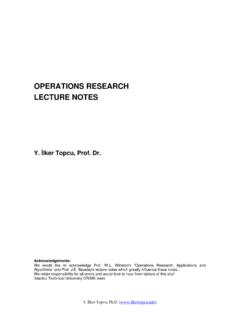
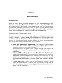
8 In Figure an image of an analog multimeter is given. With the switches on the right and left side of the multimeter, the properties of the signal to be 1-3 ITU Faculty of ELECTRICAL and Electronics Eng. Department of Electronics and Communication Eng. Figure measured are specified and the scale is adjusted. For example, if a DC current signal is to be measured, the left switch must be adjusted to DC and the right switch must be adjusted to one of the seven levels seen on the right side to make the indicator show a feasible value on the display.
9 Thus, the scale is adjusted. If for example the value to be measured is around mA, as long as the switch on the right side is adjusted to mA DC, indicator will show a value on the display. The DC current to be measured is read from the - DC display by scaling the value , where the number is proportionate to mA. As an example, if the indicator points the number on the display, since the switch on the right side is adjusted to mA, it should be read as ( mA). (The measured values for AC quantities are the root mean square (RMS/effective) values).
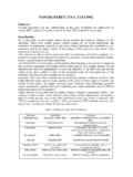
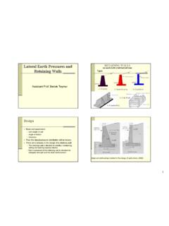
10 An image of a digital multimeter like we will use is given in Figure As it is seen on the figure, again we need to specify with a switch what we are going to measure. Then if we intend to measure a voltage or a resistance quantity we need to plug one of the probes (probe is the pointed wire that makes the contact between the measuring device and the circuit ) to the 1-4 ITU Faculty of ELECTRICAL and Electronics Eng. Department of Electronics and Communication Eng. measuring device s COM input, and the other one to the V input.