Transcription of Basics of Synthetic Aperture Radar - NASA
1 National Aeronautics and Space Administration ARSET Applied remote sensing Training @NASAARSET Basics of Synthetic Aperture Radar Erika Podest National Aeronautics and Space Administration 2 Applied remote sensing Training Program Learning Objectives By the end of this presentation, you will be able to: Understand the physics of SAR image formation Describe the interaction of SAR with the land surface Describe the necessary data preprocessing Explain what information is available from SAR National Aeronautics and Space Administration 3 Applied remote sensing Training Program The Electromagnetic Spectrum Optical sensors measure reflected solar light and only function in the daytime The surface of the Earth cannot be imaged with visible or infrared sensors when there are clouds Microwaves can penetrate through clouds and vegetation.
2 And can operate in day or night conditions National Aeronautics and Space Administration 4 Applied remote sensing Training Program Advantages and Disadvantages of Radar remote sensing Over Optical Advantages Nearly all weather capability Day or night capability Penetration through the vegetation canopy Penetration through the soil Minimal atmospheric effects Sensitivity to dielectric properties (liquid vs. frozen water) Sensitivity to structure Disadvantages Information content is different than optical and sometimes difficult to interpret Speckle effects (graininess in the image) Effects of topography National Aeronautics and Space Administration 5 Applied remote sensing Training Program Global Cloud Coverage Total fractional cloud cover annual averaged from 1983-1990, compiled using data from the International Satellite Cloud Climatology Project (ISCCP) Source: ISCCP, NASA Earth Observatory National Aeronautics and Space Administration 6 Applied remote sensing Training Program Optical vs.
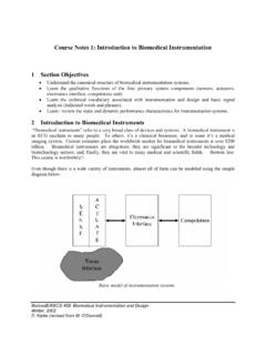
3 Radar Volcano in Kamchatka, Russia, Oct 5, 1994 Image Credit: Michigan Tech Volcanology National Aeronautics and Space Administration 7 Applied remote sensing Training Program Active and passive remote sensing passive Sensors: The source of radiant energy arises from natural sources the sun, Earth, other hot bodies Active Sensors Provide their own artificial radiant energy source for illumination Radar , Synthetic Aperture Radar (SAR), LIDAR National Aeronautics and Space Administration 8 Applied remote sensing Training Program Basic remote sensing System National Aeronautics and Space Administration 9 Applied remote sensing Training Program Basic Concepts: Down Looking vs.
4 Side Looking Radar National Aeronautics and Space Administration 10 Applied remote sensing Training Program Basic Concepts: Side Looking Radar Each pixel in the Radar image represents a complex quantity of the energy that was reflected back to the satellite The magnitude of each pixel represents the intensity of the reflected echo Credit: Paul Messina, CUNY NY, after Drury 1990, Lillesand and Kiefer, 1994 National Aeronautics and Space Administration 11 Applied remote sensing Training Program Review of Radar Image Formation can measure amplitude (the strength of the reflected echo) and phase (the position of a point in time on a waveform cycle) can only measure the part of the echo reflected back towards the antenna (backscatter) pulses travel at the speed of light Source.
5 ESA- ASAR Handbook National Aeronautics and Space Administration 12 Applied remote sensing Training Program Radar Parameters to Consider for a Study Wavelength Polarization Incidence Angle National Aeronautics and Space Administration 13 Applied remote sensing Training Program Radar Parameters: Wavelength * Wavelengths most frequently used in SAR are in parenthesis Wavelength = Speed of light frequency National Aeronautics and Space Administration 14 Applied remote sensing Training Program Radar Parameters: Wavelength Penetration is the primary factor in wavelength selection Penetration through the forest canopy or into the soil is greater with longer wavelengths Image Credit: DLR National Aeronautics and Space Administration 15 Applied remote sensing Training Program Penetration as a Function of Wavelength Waves can penetrate into vegetation and (in dry conditions) soil Generally, the longer the wavelength, the stronger the penetration into the target Image based on ESA Radar Course 2 Vegetation Dry Alluvium Dry Snow Ice X-band 3 cm C-band 5 cm L-band 23 cm National Aeronautics and Space Administration 16 Applied remote sensing Training Program Example.
6 Radar Signal Penetration into Dry Soils Different satellite images over southwest Libya The arrows indicate possible fluvial systems Image Credit: A Perego SIR-C C-Band SIR-C L-Band National Aeronautics and Space Administration 17 Applied remote sensing Training Program Example: Radar Signal Penetration into Dry Soils National Aeronautics and Space Administration 18 Applied remote sensing Training Program Example: Radar Signal Penetration into Vegetation National Aeronautics and Space Administration 19 Applied remote sensing Training Program Example: Radar Signal Penetration into Wetlands L-band is ideal for the study of wetlands because the signal penetrates through the canopy and can sense if there is standing water underneath Inundated areas appear white in the image to the right SMAP Radar Mosaic of the Amazon National Aeronautics and Space Administration 20 Applied remote sensing Training Program Radar Parameters: Polarization The Radar signal is polarized The polarizations are usually controlled between H and V: HH: Horizontal Transmit, Horizontal Receive HV: Horizontal Transmit, Vertical Receive VH: Vertical Transmit, Horizontal Receive VV: Vertical Transmit, Vertical Receive Quad-Pol Mode.
7 When all four polarizations are measured Different polarizations can determine physical properties of the object observed National Aeronautics and Space Administration 21 Applied remote sensing Training Program Example of Multiple Polarizations for Vegetation Studies Images from UAVSAR (HH, HV, VV) Pacaya-Samiria Forest Reserve in Peru National Aeronautics and Space Administration 22 Applied remote sensing Training Program Radar Parameters: Incidence Angle The angle between the direction of illumination of the Radar and the Earth s surface plane Depending on the height of the sensor, the incidence angle will change This is why the geometry of an image is different from point to point in the range direction Local Incidence Angle: accounts for local inclination of the surface influences image brightness Image Credit: Left: Ulaby et al.
8 (1981a), Right: ESA 1 cm wavelength Signal from tops, trunks, ground Signal from tops, trunks Signal from soil and subsoil Signal from wheat and soil Radar Backscatter National Aeronautics and Space Administration 24 Applied remote sensing Training Program Radar Backscatter The Radar echo contains information about the Earth s surface, which drives the reflection of the Radar signal This reflection is driven by: The frequency or wavelength: Radar parameter Polarization: Radar parameter Incidence angle: Radar parameter Dielectric constant: surface parameter Surface roughness relative to the wavelength: surface parameter Structure and orientation of objects on the surface: surface parameter National Aeronautics and Space Administration 25 Applied remote sensing Training Program Backscattering Mechanisms Density Size in relation to the wavelength Dielectric Constant Size and Orientation National Aeronautics and Space Administration 26 Applied remote sensing Training Program Surface Parameters.
9 Dielectric Constant National Aeronautics and Space Administration 27 Applied remote sensing Training Program Dielectric Properties of the Surface and its Frozen or Thawed State During the land surface freeze/thaw transition there is a change in dielectric properties of the surface This causes a notable increase in backscatter National Aeronautics and Space Administration 28 Applied remote sensing Training Program Radar Signal Interaction The Radar signal is primarily sensitive to surface structure The scale of surface relative to the wavelength determine how rough or smooth they appear and how bright or dark they will appear on the image Backscattering Mechanisms Backscattering Mechanisms National Aeronautics and Space Administration 29 Applied remote sensing Training Program Radar Backscatter in Forests National Aeronautics and Space Administration 30 Applied remote sensing Training Program Examples of Radar Interaction SMAP Radar Mosaic of the Amazon Basin April 2015 (L-band, HH, 3 km) Smooth Surface Reflection (Specular Reflection) Smooth, level surface (open water, road) Pixel Color National Aeronautics and Space Administration 31 Applied remote sensing Training Program Examples of Radar Interaction SMAP Radar Mosaic of the Amazon Basin April 2015 (L-band, HH, 3 km)
10 Rough Surface Reflection rough bare surface (deforested areas, tilled agricultural fields) Pixel Color National Aeronautics and Space Administration 32 Applied remote sensing Training Program Examples of Radar Interaction SMAP Radar Mosaic of the Amazon Basin April 2015 (L-band, HH, 3 km) Volume Scattering by Vegetation Vegetation Pixel Color National Aeronautics and Space Administration 33 Applied remote sensing Training Program Examples of Radar Interaction SMAP Radar Mosaic of the Amazon Basin April 2015 (L-band, HH, 3 km) Double Bounce Inundated Vegetation Pixel Color 1 2 National Aeronautics and Space Administration 34 Applied remote sensing Training Program Example: Detection of Oil Spills on Water UAVSAR (2 meters): HH, HV, VV National Aeronautics and Space Administration 35 Applied remote sensing Training Program Example: Land Cover Classification Brazil JERS-1 L-band 100 meter resolution Geometric and Radiometric Distortion of the Radar Signal National Aeronautics and Space Administration 37 Applied remote sensing Training Program Slant Range Distortion Source: Natural Resources Canada Slant Range Ground Range National Aeronautics and Space Administration 38 Applied remote sensing Training Program Geometric Distortion Layover Foreshortening Source: Natural Resour