Transcription of BATTERY POWER INVERTERS - Renogy
1 Version Pure Sine Wave Inverter ManualBATTERYPOWER INVERTERS700w 1000w 2000w 3000w01 Important Safety Instructions Please save these manual contains important safety, installation, and operating instructions for the inverter. The following symbols are used throughout the manual:Inverter SafetyThe INVERTERS are suitable for 12V BATTERY Banks make sure inverter is in OFF position and disconnect all AC and DC connecting when working on any circuit associated with the connect the AC output of the unit directly to an Electrical Breaker Panel/ Load Centre which is also fed from the utility POWER / connecting BATTERY terminals, ensure the polarity of the BATTERY connections is correct. Incorrect polarity may cause permanent damage to the careful when touching bare terminals of capacitors as they may retain high lethal voltages even after POWER is and wiring must comply with the Local and National Electric Codes (NEC) and must be done by a certified all of the instructions and cautions in the manual before beginning the are no serviceable parts for this inverter.
2 Do NOT disassemble or attempt to repair the sure all connections going into and from the inverter are tight. There may be sparks when making connections, therefore, make sure there are not flammable materials or gases near installation. Indicates a potentially dangerous condition. Use extreme caution when performing this a critical procedure for safe and proper operation of the a procedure or function that is important to the safe and proper operation of the Safety Information02 Do NOT let the positive (+) and negative (-) terminals of the BATTERY touch each only sealed lead-acid, flooded, or gel batteries which must be deep BATTERY gases may be present while charging. Be certain there is enough ventilation to release the careful when working with large lead acid batteries. Wear eye protection and have fresh water available in case there is contact with the BATTERY and excessive gas precipitation may damage the BATTERY plates and activate material shedding on them.
3 Too high of an equalizing charge or too long of one may cause damage. Please carefully review the specific requirements of the BATTERY used in the SafetyThe unit should be installed in a well-ventilated, cool, and dry environment. Make sure the fans of the unit and the ventilation holes are not not expose the unit to rain, moisture, snow, or liquids of any Safety03 General InformationIncluded Components0405 Table of ContentsIdentification of Parts (AC Side)Identification of Parts (DC Side)InstallationLocation RecommendationsSizing a BATTERY BankGroundingDC Side Connection06080909101111AC Side Operation13 Inverter TroubleshootingExternal FusingSpecificationsDimensions1000W700W1 415161818182000W183000W18 General InformationPure Sine WaveKey Features04 The Renogy Pure Sine Wave POWER Inverter delivers superior performance for remote off-grid applications, capable of producing cleaner, smoother, and more reliable electricity for a user s electronic Renogy POWER INVERTERS output a pure sine wave similar to the waveform of the grid POWER .
4 In a pure sine wave, the voltage rises and falls in a smooth fashion with very low harmonic distortion and cleaner utility-like and sleek designOptimized for 12 VDC system voltageClean POWER for safe operation of sensitive electronicsEasy-to-read LED indicator displayMultiple protection features (LVD, HVD, AC Overload and Over Temperature)Excellent Surge Rating : 2x the POWER Rating Ground-fault circuit interrupter(GFCI) protectionBuild-in 5 USB portTime(Seconds)Amplitude(Volts)Pure(Si ne Wavefom)This gives users stable enough POWER to operate tools, fans, lights, computers, and other electronics without any interference. Pure sine wave INVERTERS are in many cases more efficient, allowing users to use less energy and allow for more device capability. The main advantage to pure sine wave INVERTERS is that they are used to operate sensitive electronic devices that require a high quality waveform with little harmonic distortion.
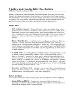
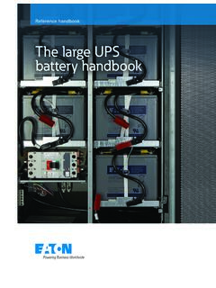
5 Almost any electronic device could be powered using a pure sine wave ComponentsThe Renogy Pure Sine Wave BATTERY INVERTERS will be shipped with inverter cables and a remotecontrol for powering the inverter on or remote controlInverter ModelGauge700W1000W2000W3000W6 AWG 3ft4 AWG 3ft4 AWG*2 3ftDoes not includeList dimensions ThicknessWire x x , 73 x x , Approx 06 Identification of Parts (AC Side)Key Parts1. High Output AC Terminals These terminals are for connecting 115V AC devices that require more than 15 amps to operate or for connection to distributed wiring that has multiple AC outlets. Remove the two screws on protective cover to access the terminals. Any AC output wiring that is directly connected must comply with US National Electric Code (NEC) wiring gauge recommendations. NEUTRAL and GROUND are bonded inside the inverter to comply with theNational Electric Code (NEC) requirement that any AC source must have a neutral to ground 2: 1000W Inverter12345678 LEFTN eutral (N)Ground(G)MiddleRightLive(L)2.
6 POWER LED (Green) When this green LED is lit, the inverter is GFCI LED (Yellow) When the yellow LED is lit, the ground fault circuit has been interrupted. Shut down the inverter and restart. Facing the front panel, the terminals are:07 Alarm If there is a buzzing sound, the BATTERY is low. The user should reduce the AC load, charge the BATTERY , and check the DC cable for excessive LED (Red) The red indicator turns on as the inverter shuts down due to overheating, overload, under voltage, or over turn off all AC appliances if the Fault LED is lit. Allow the inverter to cool before continuing. Make sure that the ventilation vents are not an inverter shutdown was preceded by a buzzing sound, there may be an excessive load in combination with low voltage or a cable Switch Controls AC Outlets USB POWER Port 5 volts / for charging tablets, smartphones, and other small Remote Switch Connection Insert wired remote switch to the connection port.
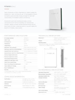
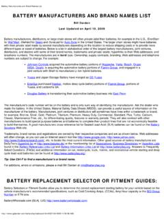
7 Set electronic AC 60Hz, up to 15amps for 2000W and 3000W models, up to amps for 700W,up to amps for switch to "remote" Terminal Positive (+) DC Input (Red) Fans Thermally Terminal Negative ( ) DC Input (Black) Terminal For insulated safety ground 3: 1000W InverterIdentification of Parts (DC Side)234109 Never install the inverter in a sealed enclosure with flooded batteries. Gas can accumulate and there is a risk of inverter should never be mounted vertically on a vertical surface since it would present a hazard for the fan opening which is crucial for coolingthe inverter. Cool, dry, well-ventilated area Heat is the worst enemy for electronic equipment. INVERTERS must be in an area where the fans are not blocked or where they are not hit directly by the sun. They should be in an area free of any kind of moisture and allow for clearance of at least 10 around the unit to provide for adequate against fire hazard the unit should be away from any flammable material, liquids, or any other combustible material.
8 The unit can spark and the consequences could be proximity to BATTERY bank prevent excessive voltage drop by keeping the unit close to the BATTERY bank and having a properly sized wire going from the BATTERY bank to the inverter. Limiting electromagnetic interference (EMI) ensure the inverter is firmly grounded to a building, vehicle, or earth grounded. Keep the inverter away from EMI receptors such as TVs, radios, and other audio/visual electronics to prevent damage/interference to the equipment. Secure inverter the inverter could be stand alone or mounted using the outlying terminals on the inverter. InstallationLocation RecommendationsEnsure installation follows the following guidelines:CAUTIONCAUTIONWARNINGWARNINGW ARNINGWARNINGMake sure inverter is in the off position before connecting not over-torque or over tighten the terminals. This could potentially damage the to the technical specifications for max wire sizes on the controller and for the maximum amperage going through wires.
9 Not install the inverter in the same compartment as the BATTERY bankbecause it could serve as a potential fire hazard. 10 ExampleA Microwave oven = 700 Watts12V BATTERY bank700 Watts to run microwave oven using the batteries as if it was a 12 VDC microwave requires 58 Amps700 Watts / 12 Volts = 58 AmpsNow that amps have been determined, the amp-hours need to be determined. The microwave will be used for approximately 3 hours a Amps * 3 hours = 174 AhAt least a 174 Ah BATTERY must be selected in order to use the 700-Watt microwave at 3 hours a day. However, determining a BATTERY size is also dependent on the BATTERY that is able to handle repeated discharge/charge Operation = 3 hoursDetermine the amount of Watts (Amps * Volts) for the load, and how long the load needs to operate each electrical appliance has technical specificationsindicating the watts, or the volts and amps required for load run-time BATTERY size depends on load watts and run-time.
10 Most loads are not constant, so estimation is very the formula Watts = Volts * AmpsDetermine Amps used for how many hours Amp-hour (Ah)Sizing a BATTERY BankFor this Renogy inverter, the BATTERY bank will be 12 volts direct current (12 VDC)This is just an example. Actual quantities vary by BATTERY capacity and rates of discharge. NOTETo POWER the microwave in the example, the user must use an inverter that is at least 1000 watts, if not Side ConnectionThe Renogy Pure Sine Wave INVERTERS come equipped with a grounding lug to appropriately ground to earth or to another designated ground (for example, a metal frame of an RV). The connections to ground must be tight and against bare metal. Whether using the inverter in a mobile application, such as an RV, or in a building, grounding is highly recommended. The recommended wire size for grounding is 10 AWG insulated copper strand wire. For more information regarding grounding, users and/or installers must consult with the Local and National Electric Codes (NEC) for more specific grounding regulations and suggestions as they can change per scenario.