Transcription of Bearings in centrifugal pumps - SKF
1 Bearings in centrifugal pumpsApplication handbook1 Table of contents 2 Preface 3 General 8 Pump Bearings 19 Ball Bearings in centrifugal pumps 28 Roller Bearings in centrifugal pumps33 Bearing technologies for the next generation pump35 Bearing installation2 PrefaceThis application handbook is one of a series of application handbooks designed to pro-vide specific application recommendations for SKF customers when used with the SKF General Catalog. It is not possible, in the limited space of this handbook, to present all the informa-tion necessary to cover every application in detail. SKF application engineers should be contacted for specific bearing recommen-dations. The higher the technical demands of an application and the more limited the available experience, the more advisable it is to make use of SKF s engineering service. We hope you find this handbook interest-ing and useful.
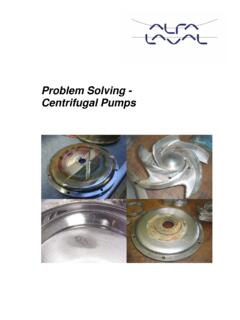
2 3 GeneralPrinciples of centrifugal pumpsA pump is a device for lifting, transferring, or moving fluids by suction or pressure from one position to another. The centrifugal pump is a type of pump that uses the kinetic energy of a rotating impeller to impart motion to the fluid, see figure The rotating impeller acceler-ates the fluid through its vanes and into the pump casing where the kinetic energy of the moving fluid is converted to potential energy at higher pressure. As the fluid leaves the impeller through the pump discharge, more fluid is drawn into the pump inlet where the pressure is lowest. This fluid passes through the impeller as still more fluid enters the impeller. There are three classifications of centrifu-gal pumps : radial flow, mixed flow and axial flow based on the direction the fluid enters the inlet (eye) of the impeller, see figure Radial and mixed flow pumps are either single or double suction designs.
3 A centrifugal pump produces head, H as a function of the rate of fluid flow, Q through the impeller, see figure Head is the energy content in the pumped fluid, expressed in meters, m (ft).Figure $FOUSJGVHBM QVNQ'MPX3 PUBUJPO""$FOUSJGVHBM QVNQ'MPX3 PUBUJPO""$FOUSJGVHBM QVNQ'MPX3 PUBUJPO""Figure Classes of centrifugal pumpsFigure ) 2&''#&1'MPX SBUF)FBER adial flowMixed flowAxial flow4 Pump OperationA pump is selected for an application to produce a desired flow and head. The performance curve of a typical radial centrifugal pump is illustrated in the figure The curve shows the head, efficiency, power requirements, and net Positive Suc-tion Head required (NPSHr) of the pump versus the hydraulic performance of a centrifugal pump is characterized by the mechanical shape and size of the impeller, using an index number called specific speed, ns, see figure The specific speed number of a pump is calculated by the following equation:ns = n Q1/2 H3/4wherens = specific speedn = pump rotational speed, r/minQ = pump flow rate, m3/s (US gallons/min) at best efficiency point, BEPH = pump total head, m(ft) at the BEP*US units are in parenthesis The characteristics of a pump based on specific speed are approximately as accord-ing to the table.
4 A centrifugal pump consists of a hydrau-lic assembly and a mechanical assembly, see figure The components of the hydraulic assembly are the impeller, casing (volute), inlet and discharge piping, and shaft seal. The components of the mechan-ical assembly are the shaft and Bearings , pump frame and housing seals, baseplate, and drive coupling or belt sheaves. For petrochemical applications, the pump industry has developed standards for the manufacture and supply of centrifugal pumps . Two important standards are the ASME/ANSI for chemical process pumps and API 610 for general refinery service pumps . These standards define the minimum technical requirements for the mechanical design of the pumps and bear-ings etc. Because of the strong American influence on petrochemical plant engi-neering, these standards have worldwide 4 QFDJGJD TQFFE OT4*643 BEJBM 7 BOF'SBODJT GMPX"YJBM GMPX Pump characteristics Specific ns Characteristic speed low 10-35 low flow (500-1750) high head medium 35-85 medium flow (1750-4250) medium head high 85-160 high flow (4250-8000) low head highest 160-300 maximum flow (8000-15000) minimum headThe centrifugal pump impeller is most typically supported on its own shaft and Bearings and driven by an electric motor, and less often by an engine or a turbine.
5 The pump shaft is connected to the driver either directly through a flexible coupling or indirectly by a belt drive. The impeller can also be rigidly connected to the motor shaft..FDIBOJDBMBTTFNCMZ)ZESBVMJDBTTFNCM ZH ydraulic assemblyImpeller/propellerSuction inletVoluteSeal ringsMechanical assemblyShaft seal Labyrinth Mechanical PackingShaftBearingsHousing/frameDrive coupling/sheave5In single stage end suction pumps , the magnitude and direction of the net axial load is most influenced by the design of the impeller. Four typical impeller designs are illustrated in the figure The semi-open impeller with pump-out vanes and the closed impeller with two wear rings and balance holes are most common in petrochemical and paper mill process point of highest pump efficiency is called the Best Efficiency Point or BEP. This is the pump design point and the operating point where the flow has the least friction and disturbance as it passes through the pump.
6 For lowest power con-sumption, the pump is operated between 80 and 100% of BEP. Because of practical considerations, it is common for a pump to operate in the range of 50 to 120% of BEP. Pump operation at a flow rate below the BEP causes poor hydraulic performance and increased hydraulic impeller loads. Pump operation above the BEP can result in cavitation and increased vibration. The NPSHr is the head at the pump inlet (suction) needed for the pump to satisfac-torily draw the fluid into the impeller. If the available head at the pump inlet, called net Positive Suction Head available (NPSHa), is less than the pump s NPSHr, cavitation will occur and performance will be reduced. Cavitation is the phenomenon that oc-curs when the local pressure of the fluid is less than its vapor pressure and local vapor is formed from the fluid. A pump operat- ing with insufficient NPSHa, experiencing cavitation, develops small vapor bubbles near its inlet that grow in size as they move further into low pressure areas of the impeller.
7 This causes unbalanced flow and pressure on the impeller. As the vapor bubbles reenter high pressure areas of the impeller, they collapse, exerting forces on the impeller that cause impeller dam-age, shaft deflection and increased bearing loading. The common nominal pump rotational speeds for small and medium size pumps are 1,500 and 3,000 r/min at 50 Hz frequency and 1,800 and 3,600 r/min at 60 Hz frequency. Other rotational speeds are possible with belt and gear driven pumps , etc. Pump Bearing LoadsThe pump Bearings support the hydraulic loads imposed on the impeller, the mass of impeller and shaft, and the loads due to the shaft coupling or belt drive. Pump Bearings keep the shaft axial end movement and lateral deflection within acceptable limits for the impeller and shaft seal. The lateral deflection is most influenced by the shaft stiffness and bearing clearance.
8 The hydraulic loads comprise of hydro-static and momentum forces from the fluid. The forces on the impeller are simplified into two components: axial load and radial load. Axial LoadThe axial hydraulic pressures acting on a single stage centrifugal pump are illustrated in the figure The axial load is equal to the sum of the forces:1. the hydrostatic force acting on the impeller s front shroud and hub (back) shroud due to the hydraulic pressures acting on the surface areas of the shrouds2. the momentum force due to the change in direction of the fluid flow through the impeller, and3. the hydrostatic force due to the hydraulic pressure acting on the impeller (suction) opening. The hydrostatic forces dominate the impeller loading. The magnitude and direction of the axial force may change during the pump start process owing to varying flow conditions in the side spaces between the impeller shrouds and casing walls.
9 The changes in flow conditions and the consequential changes in pressure distributions on the impeller shrouds result in changes to the axial 'MPX SBUF)FBE#&1&GGJDJFODZ &'' ) 2 /14)S108&3 41 (3 108&3 /14)S 0 Figure 'SPOUTISPVE)VC CBDL TISPVEF igure SJOH#BMBODF IPMFSemi-open impellerSemi-open impeller with vanesClosed impeller with one wear ringClosed impeller with two wear rings and balance holes6In pumps with open and semi-open impellers, the axial load is normally directed towards the suction side owing to the pressure on the large area of the hub shroud. Closed pump impellers with wear rings can have near balanced (zero) axial load or more usually low axial load directed towards the suction. With in-creased suction pressures, the axial load can be directed opposite to the suction. Impeller pump-out vanes and balance holes are employed to balance the axial load.
10 Pump-out vanes (also called back vanes) are small radial vanes on the hub shroud used to increase the velocity of the fluid between the hub shroud and the casing wall. This reduces the pressure of the fluid and results in reduced axial load on the impeller. The ability of pump-out vanes to reduce axial load is dependent on their clearance with the back casing holes are holes in the hub shroud used to equalize (balance) the pressure behind the impeller with that of the pump suction. Balance holes help to balance the two hydrostatic forces acting in opposite directions on the impeller shroud surfaces. SKF performed tests in which results illus-trate the influence of the balance holes on pump axial load, see figure The impel-ler without balance holes has greater axial load than the impeller with balance holes. The magnitude and direction of the axial load can change from its design value if pump-out vane clearance changes due to wear or is not set within tolerance and if balance holes become plugged with debris.