Transcription of BEE501- CONTROL SYSTEM UNIT 1 SYSTEMS AND THEIR …
1 BEE501- CONTROL SYSTEM UNIT 1 SYSTEMS AND THEIR REPRESENTATION Definition of CONTROL SYSTEM A CONTROL SYSTEM is a SYSTEM of devices or set of devices, that manages commands, directs or regulates the behavior of other device(s) or SYSTEM (s) to achieve desire results. In other words the definition of CONTROL SYSTEM can be rewritten as A CONTROL SYSTEM is a SYSTEM , which controls other SYSTEM . As the human civilization is being modernized day by day the demand of automation is increasing accordingly. Automation highly requires CONTROL of devices. Requirement of Good CONTROL SYSTEM Accuracy: Accuracy is the measurement tolerance of the instrument and defines the limits of the errors made when the instrument is used in normal operating conditions. Accuracy can be improved by using feedback elements.
2 To increase accuracy of any CONTROL SYSTEM error detector should be present in CONTROL SYSTEM . Sensitivity : The parameters of CONTROL SYSTEM are always changing with change in surrounding conditions, internal disturbance or any other parameters. This change can be expressed in terms of sensitivity. Any CONTROL SYSTEM should be insensitive to such parameters but sensitive to input signals only. Noise : An undesired input signal is known as noise. A good CONTROL SYSTEM should be able to reduce the noise effect for better performance. Stability : It is an important characteristic of CONTROL SYSTEM . For the bounded input signal, the output must be bounded and if input is zero then output must be zero then such a CONTROL SYSTEM is said to be stable SYSTEM .
3 Bandwidth : An operating frequency range decides the bandwidth of CONTROL SYSTEM . Bandwidth should be large as possible for frequency response of good controlsystem. Speed : It is the time taken by CONTROL SYSTEM to achieve its stable output. A good CONTROL SYSTEM possesses high speed. The transient period for such SYSTEM is very small. Oscillation : A small numbers of oscillation or constant oscillation of output tend to SYSTEM to be stable. Basic elements of CONTROL SYSTEM : In recent years, CONTROL SYSTEMS have gained an increasingly importance in the development and advancement of the modern civilization and technology. Figure shows the basic components of a CONTROL SYSTEM . Disregard the complexity of the SYSTEM ; it consists of an input (objective), the CONTROL SYSTEM and its output (result).
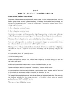
4 Practically our day-to-day activities are affected by some type of CONTROL SYSTEMS . There are two main branches of CONTROL SYSTEMS : 1) Open-loop SYSTEMS and 2) Closed-loop SYSTEMS . 1. Open-loop SYSTEMS : The open-loop SYSTEM is also called the non-feedback SYSTEM . This is the simpler of the two SYSTEMS . A simple example is illustrated by the speed CONTROL of an automobile as shown in Figure 1-2. In this open-loop SYSTEM , there is no way to ensure the actual speed is close to the desired speed automatically. The actual speed might be way off the desired speed because of the wind speed and/or road conditions, such as uphill or downhill etc. Practical Examples of Open Loop CONTROL SYSTEM 1. Electric Hand Drier - Hot air (output) comes out as long as you keep your hand under the machine, irrespective of how much your hand is dried.
5 2. Automatic Washing Machine - This machine runs according to the pre-set time irrespective of washing is completed or not. 3. Bread Toaster - This machine runs as per adjusted time irrespective of toasting is completed or not. 4. Automatic Tea/Coffee Maker - These machines also function for pre adjusted time only. 5. Timer Based Clothes Drier - This machine dries wet clothes for pre-adjusted time, it does not matter how much the clothes are dried. 6. Light Switch - Lamps glow whenever light switch is on irrespective of light is required or not. 7. Volume on Stereo SYSTEM - Volume is adjusted manually irrespective of output volume level. Advantages of Open Loop CONTROL SYSTEM 1. Simple in construction and design. 2. Economical. 3. Easy to maintain. 4. Generally stable.
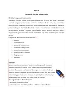
6 5. Convenient to use as output is difficult to measure. Disadvantages of Open Loop CONTROL SYSTEM 1. They are inaccurate. 2. They are unreliable. 3. Any change in output cannot be corrected automatically. 2. Closed-loop SYSTEMS : The closed-loop SYSTEM is also called the feedback SYSTEM . A simple closed- SYSTEM is shown in Figure 1-3. It has a mechanism to ensure the actual speed is close to the desired speed automatically. Practical Examples of Closed Loop CONTROL SYSTEM 1. Automatic Electric Iron - Heating elements are controlled by output temperature of the iron. 2. Servo Voltage Stabilizer - Voltage controller operates depending upon output voltage of the SYSTEM . 3. Water Level Controller - Input water is controlled by water level of the reservoir. 4. Missile Launched and Auto Tracked by Radar - The direction of missile is controlled by comparing the target and position of the missile.
7 5. An Air Conditioner - An air conditioner functions depending upon the temperature of the room. 6. Cooling SYSTEM in Car - It operates depending upon the temperature which it controls. Advantages of Closed Loop CONTROL SYSTEM 1. Closed loop CONTROL SYSTEMS are more accurate even in the presence of non-linearity. 2. Highly accurate as any error arising is corrected due to presence of feedback signal. 3. Bandwidth range is large. 4. Facilitates automation. 5. The sensitivity of SYSTEM may be made small to make SYSTEM more stable. 6. This SYSTEM is less affected by noise. Disadvantages of Closed Loop CONTROL SYSTEM 1. They are costlier. 2. They are complicated to design. 3. Required more maintenance. 4. Feedback leads to oscillatory response. 5. Overall gain is reduced due to presence of feedback.
8 6. Stability is the major problem and more care is needed to design a stable closed loop SYSTEM . Comparison of Closed Loop And Open Loop CONTROL SYSTEM Electrical Analogies of Mechanical SYSTEMS Two SYSTEMS are said to be analogous to each other if the following two conditions are satisfied. The two SYSTEMS are physically different Differential equation modelling of these two SYSTEMS are same Electrical SYSTEMS and mechanical SYSTEMS are two physically different SYSTEMS . There are two types of electrical analogies of translational mechanical SYSTEMS . Those are force voltage analogy and force current analogy. Force Voltage Analogy In force voltage analogy, the mathematical equations of translational mechanical SYSTEM are compared with mesh equations of the electrical SYSTEM .
9 Consider the following translational mechanical SYSTEM as shown in the following figure. The force balanced equation for this SYSTEM is (Equation 1) Consider the following electrical SYSTEM as shown in the following figure. This circuit consists of a resistor, an inductor and a capacitor. All these electrical elements are connected in a series. The input voltage applied to this circuit is VV volts and the current flowing through the circuit is ii Amps. Mesh equation for this circuit is (Equation 2) Substitute, in Equation 2. (Equation 3) By comparing Equation 1 and Equation 3, we will get the analogous quantities of the translational mechanical SYSTEM and electrical SYSTEM .
10 The following table shows these analogous quantities. Rotational Mechanical SYSTEM Electrical SYSTEM Torque(T) Voltage(V) Moment of Inertia(J) Inductance(L) Rotational friction coefficient(B) Resistance(R) Torsional spring constant(K) Reciprocal of Capacitance (1c)(1c) Angular Displacement( ) Charge(q) Angular Velocity( ) Current(i) Torque Voltage Analogy: In this analogy, the mathematical equations of rotational mechanical SYSTEM are compared with mesh equations of the electrical SYSTEM . Rotational mechanical SYSTEM is shown in the following figure. The torque balanced equation is (Equation 4) By comparing Equation 4 and Equation 3, we will get the analogous quantities of rotational mechanical SYSTEM and electrical SYSTEM .