Transcription of Bench Series Ovens Quincy Lab, Inc. Models 21 / 31 …
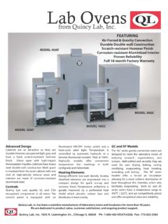
1 Bench Series Ovens Quincy Lab, Inc. Models 21 / 31 / 51. Operating Manual Standard Contents (1) Bench Series Oven Heat cycle LIGHT. (2) Adjustable chrome wire shelf POWER. LIGHT. (4) Shelf brackets HEATER. SWITCH. POWER. LIGHT. POWER. LIGHT. Not For Use With Flammable POWER. RECIRC. FAN. Solvents or Gases. model model model model . SPECIFICATIONS 21-250 21-350 31-350 51-550. INTERIOR DIMENSIONS. INCHES W x H x D (CM) W x H x D EXTERIOR DIMENSIONS. INCHES W x H x D (CM) W x H x D 83x60x90 83x60x90 83x86x90 83x60x90. TEMPERATURE RANGE. Ambient + 25F to 300 F/150 C 450 F/232 C 450 F/232 C 550 F/287 C. CONTROL STABILITY. @ 100C +/- C +/- C +/- C +/- C. @ 200C NA +/- C +/- C +/- C. STANDARD ELECTRICAL. VOLTS/AMPS 120 * 120/16* 120/16* 230 WATTS 1050 1920 1920 2850. PLUG/NEMA 5-15P* 5-20P* 5-20P* 6-20P.
2 * Standard Models voltage only, optional 230 voltage available. Check label on back of unit. WEIGHT. SHIPPING 185 185 225 195. STAND ALONE 165 165 200 170. Common Unit Construction Exterior: Powder Coated Steel Interior: Aluminized Steel (stainless optional). Insulation: Fiberglass Motor: Sealed Ball Bearing Thermo-control: Hydraulic Heater: Resistive-Tubular Incoloy Issue Rev A 1108 Quincy Lab Inc. 1925 N. Leamington Ave. Chicago, Illinois 1-800-482-HEAT (4328) PAGE 1. Copyright Quincy Lab Inc. 2008. Safety Precautions Read Operating Instructions Thoroughly Prior to Operation The Bench Series Ovens are not designed for use with any flammable solvents or gases or for materials that may contain flammable solvents or gases. Use only a grounded outlet that is rated for your model 's electrical requirement - do not use with an extension cord.
3 Oven exterior walls and doors may become hot to the touch when operating at higher set temperatures. Do not operate the oven in close proximity to any flammable solvents, gases or materials. Do not leave the oven unattended during operation, especially when processing materials that have flash point temperatures lower than the model oven's maximum operating range. Do not operate or modify the oven to operate without the motor or fan/blower. Conduct periodic maintenance as required. Set-Up & Installation Locate the oven on a suitable, clean, solid surface and maintain a minimum of 6 inches of air space between the rear electrical cover and any building or vertical surface (FIG. 1). This is important as ambient air must circulate freely through the rear air intake ports for proper cooling of the blower motor.
4 Do not cover or restrict air flow at the rear air intake ports, this will cause the motor to over-heat, shortening the motor's life and increase risk of fire. Heated exhaust air is expelled through the two small ports located just above rear electrical cover. (FIG. 2) Keep materials or building surfaces that may be susceptible to this heated exhaust air clear from rear area. Maintain a minimum 5 feet of unobstructed space above the oven to allow exhaust air to convect up and away from the air intake ports. Keep 3" of air space at the oven sides (3" from control panel cover). For units with optional Exhaust Chamber Adapter, see page 3. CLEARANCE REAR VIEW AIR FLOW. REQUIREMENTS. EXHAUST AIR. 6" minimum from wall to rear blower housing. 10". INTAKE AIR. WALL. 6". FIG. 1 FIG. 2. Electrical Plug the unit into a grounded outlet for your unit's rated voltage.
5 IMPORTANT See electrical label at right side rear electrical cover to verify your units power requirements. Isolate each model to a separate, appropriately rated circuit or breaker. Below are the NEMA plug configurations that are supplied with the various Bench Series Ovens . These configurations will also help to identify the Ovens electrical rating or power requirements. 120 Volt Units 230 Volt Units 15 AMP 20 AMP 15 AMP 20 AMP. 5-15P 5-20P 6-15P 6-20P. PAGE 2. Connecting to the Exhaust Chamber Adapter (Optional). Connect the exhaust chamber adapter with standard 3" or 4" diameter single or double-wall steel or galvanized pipe. A minimum of 4 inches of clearance CLEARANCE. should be maintained between the connected pipe REQUIREMENTS. and any building surface or material. ( ). For best performance, run a short pipe horizontally (3.)
6 Feet max.) directly through an exterior wall. For 4" minimum from wall to rear exhaust piping. vertical runs the exhaust pipe should not have more than one (1) 90 degree elbow, a maximum horizontal run of 3', and a maximum of 15' vertically. Exceeding 4". WALL. these recommendations may cause improper ventilation. Poor exhaust quality would be indicated by an excess of fumes and or vapor from around the door gasket versus what would normally be present if no exhaust venting was used. Piping run lengths can be extended beyond recommended maximums where a connection to an existing ventilation or exhaust system provide a larger pipe diameter and/or a mechanically powered draft that provides a negative pressure at the point of FIG. 3. connection. Mechanically powered vent systems work best to eliminate fumes and moisture vapors, but depending on vacuum strength at the point of connection, it may slightly reduce the oven's time-to-temperature and recovery performance.
7 Important Note about the Exhaust Chamber and Connection The optional exhaust chamber adapter is used to vent oven chamber fumes and heated moisture- laden air to a building's exterior for the purposes of minimizing excess heat, humidity or unpleasant but otherwise harmless fumes within an interior working environment. The exhaust chamber system as a whole is not designed for use to remove harmful or flammable gases or vapors since the oven itself is not rated for use with such materials. Also, the oven being electric as opposed to gas, does not produce any harmful bi-products in the process of producing heat. It is recommended that the attached exhaust chamber and piping be checked once a year for any obstruction from dust, dirt, or material process "plaque" build-up from processing certain materials.
8 Check with the manufacturer of the materials used in your process if heating the material may produce a bi-product or out gassing that may build up on the interior surface of the oven, exhaust chamber or piping and present a fire hazard over time. Contact an HVAC engineer for assistance with installation or questions regarding proper venting requirements in your specific building or location, and if any local or national fire or safety codes may apply for your application or process. Annually check exhaust piping for possible obstruction or material process build up. PAGE 3. Shelf Installation and Use Install adjustable shelf by first placing the shelf bracket rivets into the corresponding keyhole supports located on each inner side of the oven. Orientate the bracket in the "down" or " L" position.
9 This position guides the shelf in and out and protects the side wall from being scratched. The bracket may also be placed in the "up" or " " position if slightly more interior clearance is needed. Place the shelf on the brackets as shown. (FIG. 4). Each shelf will support a distributed load of 100. lbs. maximum. Do not exceed a combined total of 300 lbs. within the oven at one time. Avoid placing articles on the oven floor. Instead, use a shelf at the lowest adjustable position. Care should be taken when removing articles from the oven. Don't pull the shelf out when removing heavy loads. The shelf is not secured and loads can tip and fall forward. FIG. 4. General Operation Turn the power/recirc. fan switch to the up position. Turn heater switch to heat. Rotate the thermostat dial to the desired temperature.
10 The heat cycle light will illuminate until the set temperature is reached. Once reached, the heat cycle light will cycle on and off with the heaters, maintaining the set temperature. Typically, the oven will need to cycle at a set temperature for a minimum of 20 minutes before it will achieve equilibrium and becomes stable (see stability specs. on page 1). The heater switch in the off or cool position allows for convenient ambient air drying of articles or to help slowly or evenly cool heated articles without having to lower or change the temperature setting. Also, use this switch to allow the oven to cool before turning the fan off when using the oven at higher temperature settings. This helps to both cool the motor (prolonging it's life), and remove moisture-laden air before it condenses in the chamber, which will help prevent premature corrosion over time.