Transcription of Bendix QR-1C Double Check and Quick Release Valve
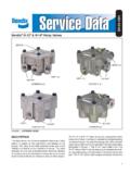
1 1 FIGURE ASD-03-904 DESCRIPTIONThe Bendix QR-1C is a dual function Valve . The Valve sprimary function is to serve the emergency side of a springbrake actuator as a Quick Release Valve . In addition, itfunctions as an anti-compound device. The Double checkvalve prevents a service and emergency brake applicationfrom occurring QR-1C Valve is generally mounted on the axle andserves two spring brake actuators. The air connections tothe QR-1C Valve are as follows:1. QR-1C Valve delivery port (2) connected to emergencyport of spring QR-1C Valve balance port (1) connected to delivery ofbrake Valve or relay Valve . NOTE: If relay Valve is installedon vehicle, it should be connected to the delivery side(not service or signal side).3. QR-1C Valve supply port (1) connected to delivery ofpark control its standard configuration the Valve is designed to deliverwithin 1 psi of control pressure. However, for specialapplications the Valve is available with greater differentialpressure or zero hysteresis.
2 QR-1C valves also come withoptional noise reducing foam crosses or silencers. SomeQR-1C valves can also come with biased Double checkvalves. These Double Check valves contain a beaded seatcap nut (Figure B). The bias design minimizes low QR-1C Double Check and Quick Release ValveMounting HolesDelivery (2)SupplyPort(1)BodyQuick ReleaseDiaphragmDeliverySealing RingExhaustCoverSealing RingDouble CheckDiaphragmBalance Port(1)Cap NutBeaded(Biased) SeatNon-BeadedIdentificationMarkFIGURE B2 OPERATIONSPRING BRAKES RELEASEDWhen the spring brakes are released, air from the park controlvalve flows through the QR-1C Valve , causing the doublecheck Valve and Quick Release diaphragms to flex and sealthe balance and exhaust ports. Air flows into the emergencyport of the spring brakes from the QR-1C Valve BRAKES APPLIEDWhen the spring brakes are applied, supply line air pressureto the Valve is exhausted through the park control Valve . Asair pressure is removed from one side of the Double checkvalve and Quick Release diaphragms, they flex in the oppositedirection opening the balance and exhaust ports.
3 Spring brakeemergency pressure is released at the exhaust port of thevalve while the small amount of air trapped between the twodiaphragms is released through the relay Valve or brake a service brake application is made with the springbrakes applied, service air enters the balance port and flowsthrough the Valve into the emergency ports of the springbrakes. This prevents the compounding of a service andspring brake application. Service air passing through thevalve flexes the Double Check and Quick Release diaphragms,sealing the supply and exhaust ports. When the serviceapplication is released, air is exhausted from the MAINTENANCEI mportant: Review the Bendix Warranty Policy beforeperforming any intrusive maintenance procedures. A warrantymay be voided if intrusive maintenance is performed duringthe warranty two vehicles operate under identical conditions, as aresult, maintenance intervals may vary. Experience is avaluable guide in determining the best maintenance intervalfor air brake system components.
4 At a minimum, theQR-1C Valve should be inspected every 12 months or 3600operating hours, whichever comes first, for proper the QR-1C Valve not meet the elements of theoperational tests noted in this document, further investigationand service of the Valve may be Block vehicle wheels and/or hold vehicle by means otherthan air Drain all air brake system Identify and disconnect air lines from Remove mounting bolts, then the relationship of the body and cover before Remove cap Remove sealing ring from cap Remove Double Check Valve Remove four Phillips head Separate the body and cover and remove the sealingring and Quick Release AND INSPECTIONC lean all metal parts in mineral spirits. Wipe all rubber partsclean. It is recommended that all rubber parts and any otherpart showing signs of wear or deterioration be replaced withgenuine Bendix Install sealing ring on cap Install Double Check Valve diaphragm in Install cap nut and torque to 150-400 inch Install sealing ring in Valve Install the Quick Release diaphragm in the Install the cover and diaphragm on body, aligning themarks made during disassembly.
5 Secure together usingthe four Phillips head screws and torque to 30-60 Re-install the QR-1C Valve and before putting the vehiclein service, perform the Operation and Leakage Tests. OPERATING AND LEAKAGE TESTSB efore performing these tests, park the vehicle on a levelsurface and hold the vehicle by means other than the With the park control Valve in the released position, notethat the spring brakes are Remove the air line connected to the QR-1C valvebalance port and apply a soap solution to the exhaustand balance port. A 1" bubble in 5 seconds is permissibleat either Reconnect the QR-1C Valve balance line; and usingthe park control Valve , park the vehicle. NOTE: A promptapplication of the spring brakes with an exhaust of air atthe QR-1C Valve exhaust Remove the air line connected to the supply port of theQR-1C Valve . With a service brake application holdapplied, apply a soap solution to the supply port andaround the seam between the body and cover. A 1" bubblein 5 seconds is permissible at the supply port.
6 Noleakage is permitted between the body and Reconnect the supply port air line. If the Valve does notfunction as described, or if leakage is excessive, it isrecommended that it be replaced with a new orremanufactured unit, or repaired with genuine Bendix Valve with exhaust port pointing down; securely tightenmounting bolts. Reconnect air lines as identified SAFETY GUIDELINESWARNING! PLEASE READ AND FOLLOWTHESE INSTRUCTIONS TO AVOIDPERSONAL INJURY OR DEATH:When working on or around a vehicle, the followinggeneral precautions should be observed at all Park the vehicle on a level surface, apply theparking brakes, and always block the wear safety Stop the engine and remove ignition key whenworking under or around the vehicle. Whenworking in the engine compartment, the engineshould be shut off and the ignition key should beremoved. Where circumstances require that theengine be in operation, EXTREME CAUTION shouldbe used to prevent personal injury resulting fromcontact with moving, rotating, leaking, heated orelectrically charged Do not attempt to install, remove, disassemble orassemble a component until you have read andthoroughly understand the recommendedprocedures.
7 Use only the proper tools and observeall precautions pertaining to use of those If the work is being performed on the vehicle s airbrake system, or any auxiliary pressurized airsystems, make certain to drain the air pressure fromall reservoirs before beginning ANY work on thevehicle. If the vehicle is equipped with an AD-IS air dryer system or a dryer reservoir module, besure to drain the purge Following the vehicle manufacturer srecommended procedures, deactivate the electricalsystem in a manner that safely removes all electricalpower from the Never exceed manufacturer s Never connect or disconnect a hose or linecontaining pressure; it may whip. Never remove acomponent or plug unless you are certain all systempressure has been Use only genuine Bendix replacement parts,components and kits. Replacement hardware,tubing, hose, fittings, etc. must be of equivalent size,type and strength as original equipment and bedesigned specifically for such applications Components with stripped threads or damaged partsshould be replaced rather than repaired.
8 Do notattempt repairs requiring machining or weldingunless specifically stated and approved by thevehicle and component Prior to returning the vehicle to service, makecertain all components and systems are restored totheir proper operating For vehicles with Antilock Traction Control (ATC),the ATC function must be disabled (ATC indicatorlamp should be ON) prior to performing any vehiclemaintenance where one or more wheels on a driveaxle are lifted off the ground and 2006 Bendix Commercial Vehicle Systems LLC. All rights reserved. 7/2006 Printed in