Transcription of BF4 Series - autonics
1 B-30BF4 Series FeaturesHigh reliability of fiber optic amplifier for convenient mounting High speed response : Max. Auto sensitivity setting(Button setting)/Remote sensitivity setting External synchronization input, mutual interference protection, self-diagnosis Reverse power polarity and short-circuit(Overcurrent) protection circuit Timer function : Selectable None / 40ms OFF Delay timer(fixed) (Standard type, remote sensitivity setting type only) Automatically selectable Light ON / Dark ON Precise detection of small target and complicated place to install 1: Frequency 1(Normal mode) : Max. , Frequency 2 : Max. The temperature or humidity mentioned in Environment indicates a non freezing or condensation typeExternal synchronizationinput typeRemote sensitivitysetting typeBF4 RPBF4 GPBF4 RBF4G BF4R-E BF4G-EBF4R-RBF4G-RResponse frequencyMax.
2 (Frequency 1), Max. (Frequency 2)Power supply12-24 VDC 10%(Ripple P-P: )Current consumptionMax. 45mALight source (modulated light)RedGreenRedGreenRedGreenRedGreenSe nsitivity adjustmentSensitivity adjustment button(ON/OFF)Operation modeAutomatic selection of Light ON/Dark ON accordance with button settingControl outputNPN or PNP open collector output Load voltage: Max. 30 VDC Load current: Max. 100mA Residual voltage - NPN: Max. 1V(load current: 100mA), Max. (load current:16mA) / PNP: Max. outputON state under unstable sensing(When the target stays for 300ms in unstable area),ON state when control output short-circuited Load voltage: Max. 30 VDC Load current: Max. 50mA Residual voltage - NPN: Max. 1V(load current: 50mA), Max. (load current:16mA) / PNP: Max.
3 CircuitReverse power polarity, short-circuit(overcurrent) protection circuitIndicatorOperation indicator : Red LED, Stability indicator : Green LED ON when the target stays in stable sensing levelInput of stop transmission function-Built-in -External synchroniza-tion function -Built-in(Gate/Trigger)-Remote sensitivity setting function--Built-in Interference prevention function 1 Built-in differential frequency mode (set by frequency 1 or 2 by ON/OFF button)Timer function(selectable)Built-in OFF delay timer, Approx. 40ms fixed-Built-in OFF delay timer, Approx. 40ms fixedAmbient illuminationSunlight : Max. 11,000 , Incandescent lamp : Max. 3,000 (Receiver illumination)Noise resistance 240V the square wave noise(pulse width : 1 ) by the noise simulatorDielectric strength1,000 VAC 50/60Hz for 1 minuteInsulation resistanceMin.
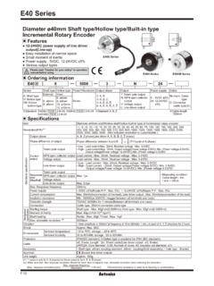
4 20M (at 500 VDC megger) amplitude or 300m/s2 at frequency of 10 to 55Hz(for 1 min.) in each of X, Y, Z directions for 2 hoursShock500m/s (approx. 50G) in each of X, Y, Z directions for 3 timesEnviron-mentAmbient illuminationSunlight : Max. 11000 , Incandescent lamp : Max. 3000 (received illumination)Ambient temperature-10 to 50 C, storage : -20 to 70 CAmbient humidity35 to 85% RH, storage :35 to 85% RHMaterialCase : Heat-resistance ABS, Cover : PCCable 4, 4-wire, Length: 2m(AWG22, Core diameter: , Number of cores: 60, Insulator out diameter : ) 4, 6-wire, Length: 2m(AWG24, Core diameter: , Number of cores: 40, Insulator out diameter : 1mm)AccessoryMounting bracket, Bolts/nutsApprovalUnit weightApprox. 65g SpecificationsPlease read Caution for your safety in operation manual before (A) Photoelectric sensor (B) Fiberopticsensor(C) Door/Areasensor (D) Proximitysensor (E) Pressuresensor (F) Rotaryencoder (G) Connector/Socket (H) (I)SSR/Powercontroller(J) Counter (K) Timer (L) Panelmeter (M)Tacho/Speed/ Pulsemeter (N)Displayunit(O)Sensorcontroller (P)Switchingmode powersupply (Q)Steppermotor&Driver&Controller(R)Grap hic/Logicpanel(S)Fieldnetworkdevice(T) Software(U) OtherFiber Optic Amplifier Connect Diode at external terminal for inductive load.
5 BF4R / BF4G BF4R-E / BF4G-E BF4RP / BF4GP BF4R-R / BF4G-R(Brown) +V(Black) Control output(White) Self-diagnosis output(Blue) 0 VLoadLoad12-24 VDC 10%+-(Brown) +V(Black) Control output(White) Self-diagnosis output(Blue) 0 VLoadLoad(Pink) External synchronization input(Orange)Emission disable input12-24 VDC 10%+-(Black) Control output(White) Self-diagnosis output(Blue) 0V(Brown) +VLoadLoad12-24 VDC 10%+-(Brown) +V(Black) Control output(White) Self-diagnosis output(Blue)0 VLoadLoad(Pink) ON input of remote sensitivity setting(Orange) OFF input of remote sensitivity setting12-24 VDC 10%+-BF4R / BF4G BF4RP / BF4GP Fiber optic sensor circuitConnectionFiber optic sensor circuitConnection(Blue)0V12-24 VDC12-24 VDC+-+-(Brown)+V(Black)Control output(White)Self-diagnosis outputMax.
6 50mAMax. 100mA LoadLoadLoadLoad(Blue)0V(Brown)+V(Black) Control output(White) Self-diagnosis outputMax. 50mAMax. 100mA Main circuitMain circuitBF4R-E / BF4G-E BF4R-R / BF4G-R Fiber optic sensor circuitConnectionFiber optic sensor circuitConnection12-24 VDC12-24 VDC+-+-(White)Self-diagnosis output(White)Self- diagnosis output(Brown)+V(Brown)+V(Pink)(Pink)(Ora nge)(Orange) LoadLoadLoadLoad (Black)Control output(Black) Control outputMax. 50mA(Blue)0V(Blue)0 VExternalsynchronization inputON input of remotesensitivity settingEmissiondisable inputOFF input of remote sensitivity settingMax. 100mA Max. 50mAMax. 100mAMain circuitMain circuit Control output diagram ConnectionsB-32BF4 Series Connect the bracket Bracket Mounting amplifier unit When mounting the amplifier Hook the front part of the amplifier on DIN rail(or bracket).
7 Press the rear part of the amplifier on DIN rail(or bracket). When releasing the amplifierPush the back of amplifier toward and lift the hole for fiber toward up then simply take it out without tools. Open the lock lever to " " direction. Insert the fiber optic cable in the amplifier slowly. (Depth: approx. 10mm) Close the lock lever to " " direction. Installation of fiber optic cable In case of using L bracket Connection of fiber optic cable & amplifier In case of using screw BF4R / BF4G / BF4RP / BF4GP / BF4R-R / BF4G-R BF4R-E / BF4G-E (unit: mm)Control output indicator(red)Stability indicator(green)Mode selection switchTimer selection switch NON:Not useing timer function OFD:OFF Delay timerSensitivity setting button Dimensions Installations Parts : 4, 8343412 41435mm DIN output indicator(red)Stability indicator(green)Mode selection switchSensitivity setting buttonExternal synchronizationselection switch TRIG:Trigger synchronization GATE:Gate synchronizationTightening torque:Max.
8 BracketFixing nut Notice: If setting bolt is tightened with over specified tightening torque, hood of fiber optic cable may be (A) Photoelectric sensor (B) Fiberopticsensor(C) Door/Areasensor (D) Proximitysensor (E) Pressuresensor (F) Rotaryencoder (G) Connector/Socket (H) (I)SSR/Powercontroller(J) Counter (K) Timer (L) Panelmeter (M)Tacho/Speed/ Pulsemeter (N)Displayunit(O)Sensorcontroller (P)Switchingmode powersupply (Q)Steppermotor&Driver&Controller(R)Grap hic/Logicpanel(S)Fieldnetworkdevice(T) Software(U) OtherFiber Optic Amplifier 1. The sensitivity can be set at unstable sensing area. When the power is OFF, the set sensitivity is saved. After completing sensitivity setting, do not move or bend fiber cable. It may not detect it properly.
9 Change the mode selection switch to SETS ensitivity settingSet interference protection functionPress ON+OFF at the same time for 2 indicator flashes continuouslySet the mode selection switch to LOCK (Completes setting)STAB indicator turns offCancellation of interferenceprotection function (Normal mode)Setting of interference protection function (Differential frequency mode)Light ONDark ONSelect the frequency 1 Select the frequency 2 Press [ON], [OFF] buttonsat the same time (Normal mode, Response time : Max. )Press [ON] button(Frequency 1, Response time : Max. )Press [OFF] button (Frequency 2, Response time : Max. )Press [ON] buttonat light ONSTAB indicator flashes one time when thedifference of sensitivity between ON and OFFis enough, but STAB indicator flashes5 times when the difference is not enoughPress [OFF] buttonat light ONPress [OFF] buttonat light OFFP ress [ON] buttonat light OFFSETLOCKSETLOCK Sensitivity adjustment Adjustment by the sensitivity setting button(Common) Light ONThe control output turns on at Light ON status and turns off at Light OFF status.
10 Setting mode Dark ONThe control output turns off at Light ON status and turns on at Light OFF status.<How to set sensitivity>Most of adjustments except & are same as Light ON stateDiffuse reflective: Press [ON] button without a sensing : Press [ON] button with a sensing stateDiffuse reflective: Press [OFF] button with a sensing : Press [OFF] button without a sensing ONLight ONMark (Low reflectance)Background(Highreflectance)<Transmitted beam> <Diffuse reflective >Mark (Low reflectance)<Transmitted beam> <Diffuse reflective >Light ONLight ONBackground(Highreflectance)OrderSettin g method Mount the fiber optic cable within sensing distance. Change the mode selection switch to [SET]. Diffuse reflective: Press [ON] button with a sensing beam: Press [ON] button without a sensing target.