Transcription of Bias Circuits for RF Devices - QSL.net
1 bias Circuits for RF Devices Iulian Rosu, YO3 DAC / VA3 IUL, A lot of RF schematics mention: bias circuit not shown ; when actually one of the most critical yet often overlooked aspects in any RF circuit design is the bias network. The bias network determines the amplifier performance over temperature as well as RF drive. The DC bias condition of the RF transistors is usually established independently of the RF design. Power efficiency, stability, noise, thermal runway, and ease to use are the main concerns when selecting a bias configuration.
2 A transistor amplifier must possess a DC biasing circuit for a couple of reasons. We would require two separate voltage supplies to furnish the desired class of bias for both the emitter-collector and the emitter-base voltages. This is in fact still done in certain applications, but biasing was invented so that these separate voltages could be obtained from but a single supply. Transistors are remarkably temperature sensitive, inviting a condition called thermal runaway. Thermal runaway will rapidly destroy a bipolar transistor, as collector current quickly and uncontrollably increases to damaging levels as the temperature rises, unless the amplifier is temperature stabilized to nullify this effect.
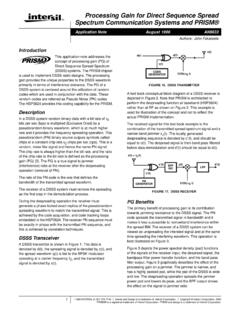
3 Amplifier bias Classes of Operation Special classes of amplifier bias levels are utilized to achieve different objectives, each with its own distinct advantages and disadvantages. The most prevalent classes of bias operation are Class A, AB, B, and C. All of these classes use circuit components to bias the transistor at a different DC. operating current, or ICQ . When a BJT does not have an input, it will have specific values of IC and VCE. These values will correspond to a specific point on the load line, point named Quiescent Current ICQ.
4 In the graph above the circuit is said to be midpoint biased since the values of IC and VCE at Quiescent- point are one-half of their maximum values. Class A single-ended amplifiers are ordinarily used only in small-signal non-power applications. Class A will generally require a constant current bias source to fix the operating point regardless of the RF drive and output. The circuit will have to have some sort of feedback to keep the output current at a fixed level, or a circuit must be created whose current is large compared to the amount of output power required ( , it is quasi class A in that the operating point movement is minimal).
5 Simply by decreasing the Icq of the amplifier by a small amount, Class AB operation can be reached. But any Class AB single-ended power amplifier will create more output distortion than a Class-A type due the output clipping of the signal's waveform. Class AB or B operations require some form of positive biasing - though the operating point will move with RF drive. This will require an open loop circuit with some sort of compensation over ambient conditions. Class C will generally require a negative bias of some kind or in most cases, the input of the transistor is tied to ground with an inductor or resistor, which is sufficient to keep the conduction angle correct.
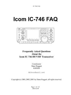
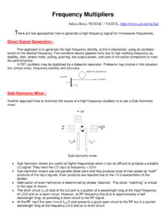
6 Typical BJT Load-Line Characteristic for Different bias Classes The most predominant biasing schemes used to obtain both temperature stabilization and single-supply operations are: base-biased emitter feedback voltage-divider emitter feedback collector-feedback diode feedback active-feedback bias All five are found in Class A and AB operation, while Class B and C amplifiers can implement other methods. Biasing Considerations for RF Bipolar Junction Transistors (BJT). Usually the manufacturer supplies in their datasheets a curve showing ft versus collector current for a bipolar transistor.
7 For good gain characteristics, it is necessary to bias the transistor at a collector current that results in maximum or near-maximum ft. On the other hand, for best noise characteristics, a low current is generally most desirable. Finally, one must consider the maximum signal level expected at the input of the transistor. The bias point must be at a sufficiently high current (and voltage) level to prevent the input signal from swinging the collector current out of the linear region of operation. It is assumed that a transistor has been chosen having a sufficient operating current level to prevent the input signal from driving the transistor into the so-called saturated region of operation, which would also be an operating condition that would prevent linear operation.
8 If the amplifier is to work over a range of temperature, have to design a bias network that maintains the bias point as the operating temperature changes. Two basic internal transistor characteristics are known to have a significant effect on the DC bias point. These are VBE and . The base-emitter voltage of a bipolar transistor decreases with increasing temperature at the rate of about mV/ C. Emitter voltage VE tends to minimize the effect because as base current increases (as VBE decreases), collector current increases, and this causes VE to increase also.
9 However, as VE increases, collector current tends to decrease. In the same time, the transistor's current gain typically increases with increasing temperature at the rate of about per degree Celsius. The BJT is quite often used as a Low Noise Amplifier due to its low cost. With a minimal number of external matching networks, the BJT can quite often produce an LNA with RF performance considerably better than an MMIC. Of equal importance is the DC performance. Although the device's RF. performance may be quite closely controlled, the variation in device DC parameters can be quite significant due to normal process variations.
10 Important for an RF BJT is that variation in hFE from device to device (up to 3 to 1) will generally not show up as a difference in RF performance. Two BJT Devices with widely different hFE's can have similar RF performance as long as the Devices are biased at the same VCE and IC. This is the primary purpose of the bias network, , to keep VCE and IC constant as the DC parameters vary from device to device. Base-biased emitter feedback works in the following way: The base resistor (RB), the V base-to emitter voltage drop (VBE), and the emitter resistor (RE), are all in series.