Transcription of Bidirectional AC/DC or DC/AC converter for Electrical ...
1 Bidirectional AC/DC or DC/AC converter for Electrical Vehicle and DC or AC Grid Santhosh Kumar R. ,Mrs. Arutselvi Nagammai P.. Computer Application in Industrial Drives, Dept of EEE, The Oxford College of Engineering (VTU),Bangalore-560068, Karnataka, India . Asst Professor, Dept of EEE , The Oxford College of Engineering (VTU), Bangalore-560068,Karnataka, India 1. Abstract This paper presents a new concept of Bidirectional AC to DC converter or DC to AC inverter is proposed in this project. Here for Bidirectional operation extra boost converters and extra converts are not needed. A single three-phase converter is enough to operate the AC traction motor, connect to AC grid, and to DC grid (as boost converter ). Extra tripping switching are used here for these operations.
2 The same system is operated for 5 states. These states can be implemented in the simulation and a prototype is made to do the same. Keywords Bidirectional converter , electric vehicle, integrated converter , machine inductance, vehicle-to-grid (V2G). I. INTRODUCTION. The multipurpose use of the power electronic converter in the drive train of an electric vehicle has become an interesting topic for minimizing the system size, weight, and cost. The weight and size of the converter are challenging issues in the case of on-board chargers which otherwise provides the flexibility of charging the vehicle anywhere. The vehicle is not driven during the period of charging, and hence, the traction motor and inverter of the power train can be used as an integral part of the converter .
3 The windings of the traction motor can serve as the inductors of the power converter along with power devices of the traction inverter to transfer power. The power converter of the electric vehicle can draw power from the grid when it requires, and also can deliver power to the grid in the peak time when the grid needs power. During a significant part of the day, most vehicles remain idle in the parking lot when the integrated power converter can use the traction motor and its drive to transfer power to the research activities for integrating the battery charging system with the traction drive have been reported in [1] and [2].In one approach, the traction motor windings have been used as the inductors for the converter to develop the charging system without any additional component [3].
4 The three-phase supply is connected with each phase of the machine and the battery is always connected to the dc bus. The research showed the use of a poly-phase machine for the charger. In this paper, an integrated motor converter is proposed that can be used as the traction motor drive, a battery charger, and a power converter to transfer energy from vehicle- to-grid (V2G) through reconfiguration of the inverter topology using relays or contactors. The traction inverter with the proposed reconfiguration method can also transfer power from the vehicle to a dc grid and from a dc grid to the vehicle using the traction motor windings with the appropriate relay settings. The three phase machine windings and the three inverter phase legs can be utilized with an interleaved configuration to distribute the current and reduce the converter switching stresses.
5 The battery voltage is increased in the boost mode to an output reference voltage level within the limits of the machine ratings. The proposed converter system can also be used for transferring power between a single-phase ac grid and the vehicle in either direction without any extra component. The rated conditions of the motor and utility interface are quite similar. Santosh, Arutselvi Page 150. II. converter TOPOLOGY. Different types of topologies have been developed for electric vehicles for battery charging and Bidirectional power flow between the battery and the power supply. However, the traction inverter uses the standard six-switch configuration that has elements of the various power converter topologies. The proposed converter topology utilizing the traction inverter along with the switches used for reconfiguration is shown in Fig.
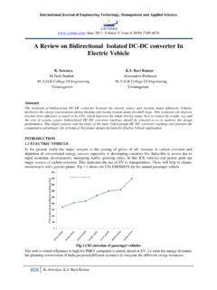
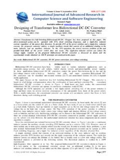
6 1(a) and (b) shows the detailed switch or relay arrangements required for different modes of operations. Several different configurations can be obtained by appropriate positioning of the switches, which results in a novel methodology for Bidirectional power transfer between a vehicle battery and dc or a c grid. Including the use of the topology as the traction inverter during vehicle operation this power converter can be operated in five different modes: 1) Power flow from the battery to the dc grid, 2) Power flow from the dc grid to the battery, 3) Traction mode, 4) Power flow from the battery to single-phase ac grid and 5) Power flow from a single-phase ac grid to the battery. converter with switches capable of interfacing with both ac and dc grid (a) combined and (b) details.
7 Fig. 1(b) shows the details of the configuration in the routing Fig. 1. converter with switches capable of interfacing with both ac and dc grid (a) combined and (b). details. Table I switch positions and converter states box with the switches which relates to the operations Santosh, Arutselvi Page 151. of the switches according to table 1 The terminal numbers are shown in Fig. 1(b) inside the switches which are changed to different positions for the different configurations. TABLE I. Switch State 1 State 2. Switch1 Pole positions: 1 and 3 Pole positions: 2 and 4. Switch2 1 and 2 disconnected 1 and 2 disconnected Pole positions: 1 and 3 Pole positions: 1 and 3. Switch3 Pole positions: 1 and 3 Pole positions: 2 and 4. Switch4 1 and 2, and 3 and 4 1 and 2, and 3 and 4.
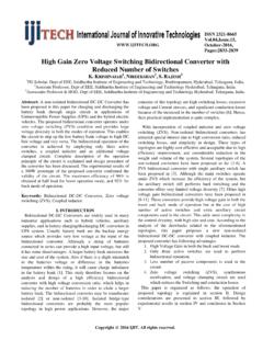
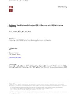
8 Disconnected connected Switch5 1 and 2 disconnected 1 and 2 connected Table 1: Switch positions and converter states When the converter is to connect to a dc grid, Switch 4 will be in State 1 to isolate from the ac grid. When the converter is to connect to an ac grid, Switch 5 will be in State 1 to isolate from the dc grid. Thus, the traction converter can be connected to either a dc or an ac grid. Fig. 2 shows the OFF condition where all the switches are in State 1; in this situation, there will be no power transfer. If there is any fault in one or multiple phases in the motor the converter configuration will be switched to State 1 as shown in Fig. 2, and there will be no power transfer between the grid and the battery. The usual protection schemes for a traction inverter will take over.
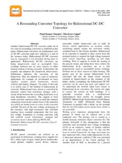
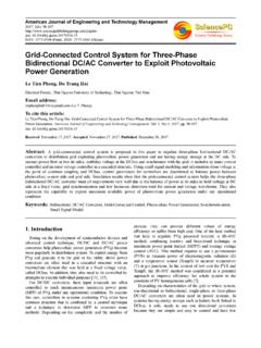
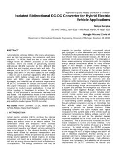
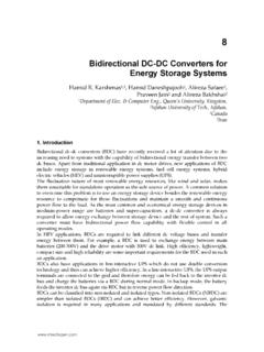
9 The system has inherent fault protection capability, and extra protection is not needed. Fig 2. (OFF condition) Circuit with all switches in State 1. Power is transferred from the vehicle battery to the dc grid using the boost mode of operation for the converter with Switch 2 and Switch 5 in State 2, and the other switches in State 1; power from the vehicle battery to the dc grid can also be transferred in buck mode with Switch 3 and Switch 4 in State 1 and the other switches in State 2. When power transfer is needed from dc grid to the vehicle, Switch 2 and Switch 5 are in State 2 for buck operation and Switch 3 and Switch 4 are in State 1 for boost operation. From Santosh, Arutselvi Page 152. Fig. 3, operating mode 1 in Fig. 3 and operating mode 2 in Fig.
10 4 have been verified in simulation. Operating mode 1 is experimentally verified using two types of machines. Although, operating mode 2 in Fig. 4 is different from operating mode 1, the converter is symmetrical for these two modes and for experiments they are similar. Therefore, verifying operating mode 1 experimentally is sufficient for both the modes. Fig. 3. Circuit with Switch 2 and Switch5 in State 2 for V2G boost or G2V buck operation with vehicle side inductors interleaved. Fig. 4. Circuit with Switch 3 and Switch 4 are in State 1 for V2G buck or G2V boost operation with dc grid side inductors interleaved. It can be observed that forV2G boost operation, the interleaved technique can be applied on the battery side with the three inductances and three legs of the converter ; for G2V boost operation, the interleaved technique can be applied on the dc grid side to reduce the switching stresses.