Transcription of BLACKMER LIQUEFIED GAS PUMPS …
1 BLACKMER LIQUEFIED GAS PUMPS 960417 INSTRUCTIONS NO. 501-C00 Section Effective Replaces 501 Aug 2010 Aug 2008 FOR LP-GAS AND NH3 SERVICE TRUCK AND BASE MOUNTED INSTALLATION OPERATION AND MAINTENANCE INSTRUCTIONS MODELS: LGLD2E, LGL2E, LGLD3F, LGL3F and discontinued LGLD3E, LGL3E Patent Protected by Patent 6030191 and Related Foreign Patents. TABLE OF CONTENTS Page SAFETY 1 PUMP DATA Pump 2 Technical 2 Initial Pump Start Up 2 GENERAL INSTALLATION AND OPERATION Welded 3 Pre-Installation Cleaning .. 3 Location and 3 Pump Relief Valve and Bypass Valve .. 4 Check 4 Pump 4 MOTOR DRIVEN PUMPS Pump 4 Coupling 5 V-Belt Drive.
2 5 V-Belt Disassembly .. 5 Pre-Start Up Check List .. 6 Start Up TRUCK MOUNTED PUMPS Truck 6 Pump Drive .. 6 Hydraulic 7 Pre-Start Up Check List .. 7 Start Up Pump 8 MAINTENANCE 8 8 Vane 9 Pump 9 Pump 10 TROUBLE 11 NOTE: Numbers in parentheses following individual parts indicate reference numbers on BLACKMER Parts List 501-C01 BLACKMER pump manuals and parts lists may be obtained from BLACKMER 's website ( ) or by contacting BLACKMER Customer Service. SAFETY DATA This is a SAFETY ALERT SYMBOL. When you see this symbol on the product, or in the manual, look for one of the following signal words and be alert to the potential for personal injury, death or major property damage Warns of hazards that WILL cause serious personal injury, death or major property damage.
3 Warns of hazards that CAN cause serious personal injury, death or major property damage. Warns of hazards that CAN cause personal injury or property damage. NOTICE: Indicates special instructions which are very important and must be followed. NOTICE: BLACKMER LIQUEFIED gas PUMPS MUST only be installed in systems which have been designed by qualified engineering personnel. The system MUST conform to all applicable local and national regulations and safety standards. This manual is intended to assist in the installation and operation of the BLACKMER LIQUEFIED gas PUMPS , and MUST be kept with the pump. BLACKMER LIQUEFIED gas pump service shall be performed by qualified technicians ONLY. Service shall conform to all applicable local and national regulations and safety standards.
4 Thoroughly review this manual, all Instructions and hazard warnings, BEFORE performing any work on the BLACKMER LIQUEFIED gas PUMPS . Maintain ALL system and BLACKMER LIQUEFIED gas pump operation and hazard warning decals. 501-C00 Page 2/12 SAFETY DATA Hazardous machinery can cause serious personal injury. Failure to set the vehicle emergency brake and chock wheels before performing service can cause severe personal injury or property damage Hazardous voltage. Can shock, burn or cause death. Failure to disconnect and lockout electrical power before attempting maintenance can cause shock, burns or death Hazardous machinery can cause serious personal injury. Failure to disconnect and lockout electrical power or engine drive before attempting maintenance can cause severe personal injury or death Do not operate without guard in place Operation without guards in place can cause serious personal injury, major property damage, or death.
5 Hazardous pressure can cause serious personal injury or property damage Disconnecting fluid or pressure containment components during pump operation can cause serious personal injury or property damage. Hazardous pressure can cause serious personal injury or property damage Failure to relieve system pressure prior to performing pump service can cause serious personal injury or property damage. Systems with meters will still be pressurized even after the hose is emptied Hazardous or toxic fluids can cause serious injury. If pumping hazardous or toxic fluids, system must be flushed and decontaminated, inside and out, prior to performing service or maintenance PUMP DATA PUMP IDENTIFICATION A pump Identification tag, containing the pump serial number, number, and model designation, is attached to each pump.
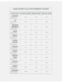
6 It is recommended that the data from this tag be recorded and filed for future reference. If replacement parts are needed, or if information pertaining to the pump is required, this data must be furnished to a BLACKMER representative. TECHNICAL DATA Models LGLD2E LGL2E LGLD3F LGL3F Torque required @100 psi ( bar) 48 lbs ft (65 Nm) 89 lbs ft (121 Nm) Maximum Pump Speed @ Max. Differential Press. 640 RPM 800 RPM* Maximum Differential Pressure 150 PSI ( Bar) Maximum Operating Temperature 240 F (115 C) Maximum Working Pressure 350 PSI ( Bar) * LGLD3E and LGL3E are rated at 640 RPM maximum. Technical Data is for standard materials of construction. Consult BLACKMER Material Specs for optional materials of construction. These PUMPS are listed by Underwriters Laboratories for LIQUEFIED petroleum gas and NH3 service.
7 INITIAL PUMP START UP INFORMATION Model No.: _____ Serial No.: _____ ID No.: _____ Date of Installation: _____ Inlet Gauge Reading: _____ Discharge Gauge Reading: _____ Flow Rate: _____ 501-C00 Page 3/12 GENERAL INSTALLATION AND OPERATION NOTICE: BLACKMER PUMPS must only be installed in systems designed by qualified engineering personnel. System design must conform with all applicable regulations and codes and provide warning of all system hazards. NOTICE: This pump shall be installed in accordance with the requirements of NFPA 58, all applicable local, state and national regulations. WELDED CONNECTIONS NOTICE: PUMPS with welded connections contain three non-metallic O-ring seals that will be damaged if welding is done with these O-rings installed.
8 Prior to welding the piping, remove the O-rings from under the inlet flange, outlet flange and relief valve cover as indicated in Figure 1. Reinstall the inlet and outlet flanges. Weld the piping to the the inlet and outlet flanges. After the welding is complete, reinstall the O-rings. Figure 1 PRE-INSTALLATION CLEANING NOTICE: New PUMPS contain residual test fluid and rust inhibitor. If necessary, flush pump prior to use. Foreign matter entering the pump WILL cause extensive damage. The supply tank and intake piping MUST be cleaned and flushed prior to pump installation and operation. LOCATION AND PIPING Pump life and performance will be significantly reduced when installed in an improperly designed system. Before starting the layout and installation of the piping system, review the following suggestions: 1.
9 Locate the pump as near as possible to the source of supply to avoid excessive inlet pipe friction. 2. The inlet piping and fittings should be at least as large as the intake port on the pump. Slope the pipe downward to the pump, and do not install any upward loops. Minimize the number of intake line fittings and eliminate restrictions such as sharp bends; globe valves, unnecessary elbows, and undersized strainers. 3. A strainer must be installed in the inlet line to protect the pump from foreign matter. Locate the strainer at least 24" ( ) from the pump. Strainers must have a net open area of at least four times the area of the intake piping, and must be cleaned regularly to avoid pump starvation. 4. The intake and discharge piping system must be free of all leaks. 5. Expansion joints, placed at least 36" ( ) from the pump, will compensate for expansion and contraction of the pipes.
10 Contact the flexible connector/hose manufacturer for required maintenance/care and design assistance in their use. 6. ALL piping and fittings MUST be properly supported to prevent any piping loads from being placed on the pump. 7. Check alignment of pipes to pump to avoid strains which might later cause misalignment. See Figure 2. Unbolt flanges or break union joints. Pipes must not spring away or drop down. After the pump has been in operation for a week or two, completely recheck alignment. Figure 2 8. Install pressure gauges in the NPT ports provided in the pump casing to check pump performance at start up. 9. The use of a or 2 vapor return line will speed up delivery by preventing pressure build up at the receiving tank and pressure reduction in the supply tank. 10. Keeping the LIQUEFIED gas systems full of liquid, even when idle, will keep the O-rings from changing shape, shrinking or super cooling.