Transcription of BLACKMER LLIQUEFIED GGAS PPUMPS …
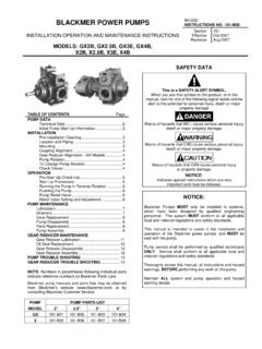
1 BLACKMER LLIQUEFIED ggas PPUMPSFFOORR CCOO2 SSEERRVVIICCEE TTRRUUCCKK AANNDD BBAASSEE MMOOUUNNTTEEDDINSTALLATION, OPERATION, AND MAINTENANCE INSTRUCTIONSMODELS: CRL4 Discontinued Model: TCRL4 & TCRLF4A962009 instructions NO. 701-C00 Page 1 of 12 Section700 EffectiveJune 2001 Replaces785/G Feb 1988 TABLE OF CONTENTSPageSAFETY Start Up Information ..2 Pump With Welded and Operation - CRL Motor Cleaning ..3 Location and Mounting ..3 Coupling Alignment ..3V-Belt Drive ..4 Internal Pump Relief Valve and Bypass Valve ..4 Pump Change Pump Rotation ..5 Pre-Start Up Check Up Procedures ..5 Relief Valve Setting and Adjustment ..5 Installation and Operation - CRL Truck Cleaning.
2 6 Location and Inlet ..6 Pump Drive ..6 Internal Pump Relief Valve and Bypass Valve ..7 Pump Change Pump Rotation ..7 Pre-Start Up Check Up Procedures ..7 Relief Valve Setting and Adjustment ..8 Pump Replacement ..9 Pump Assembly ..9 GENERAL PUMP : BLACKMER CO2pumps MUST only be installed insystems which have been designed by qualifiedengineering personnel. The system MUST conform toall applicable local and national regulations and manual is intended to assist in the installationand operation of the BLACKMER CO2pumps, and MUSTbe kept with the CO2pump service shall be performed byqualified technicians ONLY. Service shall conform toall applicable local and national regulations and review this manual, all instructions andhazard warnings, BEFORE performing any work onthe BLACKMER ALL system and BLACKMER CO2 pumpoperation and hazard warning DATANOTE.
3 Numbers in parentheses following individualparts indicate reference numbers on the correspondingBlackmer Parts is a SAFETY ALERT you see this symbol on the product, or in the manual, look forone of the following signal words and be alert to the potential forpersonal injury, death or major proper ty of hazards that WILL cause serious personal injury, death or major proper ty of hazards that CAN cause serious personal injury, death or major proper ty of hazards that CAN cause personal injuryor proper ty :Indicates special instructions which are veryimpor tant and must be FLUID ORPRESSURE CONTAINMENTCOMPONENTS DURING PUMPOPERATION CAN CAUSE SERIOUSPERSONAL INJURY, DEATH OR MAJORPROPERTY pressurecan cause personal injury orproperty DATAFAILURE TO DISCONNECT ANDLOCKOUT ELECTRICAL POWERBEFORE ATTEMPTING MAINTENANCECAN CAUSE SHOCK, BURNS shock.
4 Burn or cause cancause seriouspersonal TO DISCONNECT ANDLOCKOUT ELECTRICAL POWERBEFORE ATTEMPTING MAINTENANCECAN CAUSE SERIOUS PERSONALINJURY OR or toxicfluids can causeserious PUMPING HAZARDOUS FLUIDSSYSTEM MUST BE FLUSHED PRIORTO PERFORMING NOT ATTEMPT TO OPEN THE PUMPUNTIL YOU HAVE BLED OFF THEPRESSURE. ON SYSTEMS WITHMETERS, THE DIFFERENTIAL VALVEWILL KEEP LIQUID UNDER PRESSUREIN THE PUMP, METER AND PIPINGEVEN WHEN THE HOSE IS pressurecan cause personalinjury or DATAM odel Designations:Motor Drive & Truck MountCRL4 DiscontinuedTCRL4, TCRLF4 ATorque Required @ 100 psi205 lbs ft ( bar)(278 Nm)Maximum Temperature240oF (115oC) Minimum Temperature- 30oF (- 34oC)Maximum Pump Speed640 RPMM aximum Differential Pressure100 psi ( bar)Maximum Working Pressure525 psi ( bar)(Inlet Pressure + Differential Pressure)INITIAL START UP INFORMATIONM odel of Installation:Discharge Gauge Reading:Inlet Gauge Reading:Flow Rate.
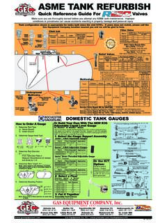
5 TECHNICAL DATAPUMP WITH WELDED CONNECTIONSNOTICE:FOR PIPING CONNECTIONS REQUIRING WELDING THEPUMP S NON-METALLIC O-RINGS MUST BE REMOVEDPRIOR TO WELDING. FAILURE TO DO SO WILLDAMAGE THE welding the piping, remove the O-rings from underthe inlet flange, outlet flange and relief valve cover asindicated in Figure 1. Reinstall the inlet and outlet flanges. Weld the piping to thethe inlet and outlet flanges. After the welding is complete,reinstall the 12 FAILURE TO SET THE VEHICLEEMERGENCY BRAKE AND CHOCKWHEELS BEFORE PERFORMINGSERVICE CAN CAUSE SEVEREPERSONAL INJURY OR machinerycan cause severepersonal injury orproperty TO RELIEVE SYSTEMPRESSURE PRIOR TO PERFORMINGPUMP SERVICE OR MAINTENANCECAN CAUSE PERSONAL INJURY ORPROPERTY pressurecan cause personalinjury or :THIS PUMP CONTAINS SOME RESIDUAL TEST FLUIDAND RUST INHIBITOR.
6 IF NECESSARY, FLUSH PUMPPRIOR TO shock, burn or cause , ground and wire to local andNational Electrical Code an all-leg disconnect switch nearthe unit and lockout electrical powerbefore installation or supply MUST match motor equipped with thermal protection automaticallydisconnect motor electrical circuit when overload can start unexpectedly and without : BLACKMER CO2 PUMPS MUST ONLY BE INSTALLEDIN SYSTEMS DESIGNED BY QUALIFIED ENGINEERINGPERSONNEL. SYSTEM DESIGN MUST CONFORMWITH ALL APPLICABLE REGULATIONS AND CODESAND PROVIDE WARNING OF ALL SYSTEM AND OPERATION CRL BASE MOUNTED MOTOR DRIVEN PUMPSPRE-INSTALLATION CLEANINGF oreign matter entering the pump WILL cause extensivedamage.
7 The supply tank and intake piping MUST be cleanedand flushed prior to pump installation and AND PIPINGAn improperly designed piping system or improper unitinstallation WILL significantly reduce pump performance andlife. BLACKMER recommends the following piping system layoutand unit installation. See Figure To minimize intake losses, locate the pump as close aspossible to the source of supply and a minimum of twofeet ( m) below the tank Intake piping and fittings MUST be at least as large indiameter as the pump intake connection. Inlet piping mustbe Use high strength Schedule 80 Minimize the number of intake line fittings (valves, elbows,etc.)
8 And piping turns or bends. The nearest fitting on theintake line must be at least 6 inches (152 mm) from thepump to permit access to the pump relief valve .5. Install an intake strainer 5 - 10 pipe diameters from thepump intake. The strainer must have a net open area of atleast four times the area of the intake pipe. Strainers mustbe cleaned regularly to avoid pump Intake and discharge piping MUST be free of all To facilitate piping expansion and contraction, expansionjoints must be placed 3 feet ( m) from the pump intakeand ALL piping and fittings MUST be properly supported toprevent any piping loads from being placed on the Install pressure gauges in the NPT ports provided in thepump casing to check pump performance at start The use a vapor return line will speed up delivery bypreventing back pressure from building up at the receivingtank and reducing pressure in the supply Keeping the liquefied gas systems full of liquid, even whenidle, will keep the O-rings from changing shape, shrinkingor super cooling.
9 Evaporation of liquefied gas leaves anabrasive powder on the surface which can cause wear tothe pump, meter, and MOUNTINGP ermanently mount the unit by securing the base plate withadequately sized anchor bolts to a level concrete floorfollowing recommendedindustry standards (SeeFigure 3). A solid foundationwill reduce system noise andvibration, and will improvepump performance. Refer toANSI/HI standards or asuitable pump handbook forinformation on typical pumpmounting and coupling alignmentafter pump and baseassembly is secured to 3 BOLTBASESTANDARDPIPEWASHERCOUPLING ALIGNMENTThe pump must be directly coupled to a gear, gear reducer,and/or driver with a flexible angular and parallel coupling alignment MUST bemaintained between the pump, gear reducer, motor, etc.
10 Inaccordance with manufacturer s instructions . See Figure To check for parallel alignment, the use of a dial indicator ispreferred. If a dial indicator is not available use a straightedge. Turn both shafts by hand, checking the readingthrough one complete revolution. Maximum offset must beless than .005" (125 microns).2. To check for angular alignment, insert a feeler gaugebetween the coupling halves. Check the spacing in 90degree increments around the coupling (four check points).Maximum variation must not exceed .005" (125 microns).Figure 4 - Alignment Check3 Storage TankFigure 2 UnionsBypass ValveGate or BallValvesIntake Connectionfor unloading tankcars or tank trucksDo no startpump unlessthis valve StorageTankDischargeStrainer4 OPERATION WITHOUT GUARDS INPLACE CAN CAUSE SERIOUSPERSONAL INJURY, MAJORPROPERTY DAMAGE OR cancause seriouspersonal AND OPERATION CRL BASE MOUNTED MOTOR DRIVEN PUMPSV-BELT DRIVEB lackmer also offers V-belt drive for CRL pumps.