Transcription of Blodgett, O.W. and Miller, D.K. Welded Connections ...
1 Blodgett, and Miller, Welded Connections . Structural Engineering Handbook Ed. Chen Wai-Fah Boca Raton: CRC Press LLC, 1999. Welded Connections Introduction Joint and Weld Terminology Determining Weld Size Principles of Design Welded Joint Details Design Examples of Specific Components Understanding Ductile Behavior Materials connection Details Ductile Behavior in Seismic Sections Requirements Blodgett and Assessment D. K. Miller Terms The Lincoln Electric Company, Cleveland, References OH Further Reading Introduction Arc welding has become a popular, widely used method for making steel structures more economical. Although not a new process, welding is still often misunderstood.
2 Perhaps some of the confusion results from the complexity of the technology. To effectively and economically design a building that is to be Welded , the engineer should have a knowledge of metallurgy, fatigue, fracture control, weld design, welding processes, welding procedure variables, nondestructive testing, and welding economics. Fortunately, excellent references are readily available, and industry codes specify the minimum standards that are required to be met. Finally, the industry is relatively mature. Although new developments are made every year, the fundamentals of welding are well understood, and many experienced engineers may be consulted for assistance.
3 Welding is the only joining method that creates a truly one-piece member. All the components of a Welded steel structure act in unison, efficiently and effectively transferring loads from one piece to an- other. Only a minimum amount of material is required when welding is used for joining. Alternative joining methods, such as bolting, are generally more expensive and require the use of lapped plates and angles, increasing the number of pieces required for construction. With Welded construction, various materials with different tensile strengths may be mixed, and otherwise unattainable shapes can be achieved. Along with these advantages, however, comes one significant drawback: any prob- lems experienced in one element of a member may be transferred to another.
4 For example, a crack that exists in the flange of a beam may propagate through welds into a column flange. This means c1999 by CRC Press LLC. that, particularly in a dynamically loaded structure that is to be joined by welding, all details must be carefully controlled. Interrupted, non-continuous backing bars, tack welds, and even seemingly minor arc strikes have resulted in cracks propagating through primary members. In order to best utilize the unique capabilities of welding, it is imperative to consider the entire design fabrication erection sequence. A properly designed Welded connection not only transfers stresses safely, but also is economical to fabricate.
5 Successful integration of design, welding processes, metallurgical considerations, inspection criteria, and in-service inspection depends upon mutual trust and free communication between the engineer and the fabricator. Joint and Weld Terminology A Welded connection consists of two or more pieces of base metal joined by weld metal. Engineers determine joint type and generally specify weld type and the required throat dimension. Fabricators select the joint details to be used. Joint Types When pieces of steel are brought together to form a joint, they will assume one of the five configurations presented in Figure Of the five, butt, tee, corner, and lap joints are common in construction.
6 Coverplates on rolled beams, and angles to gusset plates would be examples of lap joints. Edge joints are more common for sheet metal applications. Joint types are merely descriptions of the relative positioning of the materials; the joint type does not imply a specific type of weld. FIGURE : Joint types. (Courtesy of The Lincoln Electric Company. With permission.). Weld Types Welds may be placed into three major categories: groove welds, fillet welds, and plug or slot welds (see Figure ). For groove welds, there are two subcategories: complete joint penetration (CJP) groove welds and partial joint penetration (PJP) groove welds (see Figure ).
7 Plug welds are commonly used to weld decking to structural supports. Groove and fillet welds are of prime interest for major structural Connections . In Figure , terminology associated with groove welds and fillet welds is illustrated. Of great interest to the designer is the dimension noted as the throat. The throat is theoretically the weakest plane in the weld. This generally governs the strength of the Welded connection . c1999 by CRC Press LLC. FIGURE : Major weld types. (Courtesy of The Lincoln Electric Company. With permission.). FIGURE : Types of groove welds. (Courtesy of The Lincoln Electric Company. With permission.)
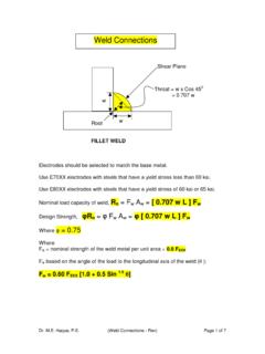
8 Fillet Welds Fillet welds have a triangular cross-section and are applied to the surface of the materials they join. Fillet welds by themselves do not fully fuse the cross-sectional areas of parts they join, although it is still possible to develop full-strength Connections with fillet welds. The size of a fillet weld is usually determined by measuring the leg size, even though the weld is designed by determining the required throat size. For equal-legged, flat-faced fillet welds applied to plates that are oriented 90 apart, the throat dimension is found by multiplying the leg size by ( , sine 45 ). Complete Joint Penetration (CJP) Groove Welds By definition, CJP groove welds have a throat dimension equal to the thickness of the plate they join (see Figure ).
9 For prequalified welding procedure specifications, the American Welding Society (AWS) [9] Structural Welding Code requires backing (see Weld Backing) if a CJP weld is made from one side, and back gouging if a CJP weld is made from both sides. This ensures complete fusion throughout the thickness of the material being joined. Otherwise, procedure qualification testing is required to prove that the full throat is developed. A special exception to this is applied to tubular Connections whose CJP groove welds may be made from one side without backing. c1999 by CRC Press LLC. FIGURE : Weld terminology. (Courtesy of The Lincoln Electric Company.)
10 With permission.). Partial Joint Penetration (PJP) Groove Welds A PJP groove weld is one that, by definition, has a throat dimension less than the thickness of the materials it joins (see Figure ). An effective throat is associated with a PJP groove weld (see Figure ). This term is used to delineate the difference between the depth of groove preparation FIGURE : PJP groove welds: E vs. S . (Courtesy of The Lincoln Electric Company. With permission.). c1999 by CRC Press LLC. and the probable depth of fusion that will be achieved. When submerged arc welding (which has inherently deep penetration) is used, and the weld groove included angle is 60 , the [9] code allows the designer to rely on the full depth of joint preparation to be used for delivering the required throat dimension.