Transcription of Bluetooth nBlueTM BR-LE4.0-S2A - Blue Radios
1 Page 1 of 7 nBlue Module Summary Datasheet Copyright 2002-2014 BlueRadios, Inc. 8310 S. Valley Highway, Suite 275 Englewood, CO 80112 USA (303)-957-1003 Bluetooth Low Energy Single Mode Class 1 SoC Module nBlueTM (CC2540) AT HOME. AT WORK. ON THE ROAD. USING Bluetooth LOW ENERGY WIRELESS TECHNOLOGY MEANS TOTAL FREEDOM FROM THE CONSTRAINTS AND CLUTTER OF WIRES IN YOUR LIFE. FCC, IC, CE, RoHS, and Bluetooth Certified ISM module. Utilizes the TI CC2540 SoC with 256K Flash, 8K RAM. Over 150 meter (500 ft) line of site (LOS) distance with integrated antenna. Can be externally controlled via simple ASCII AT commands over the UART or programmed with custom applications embedded in the module. Available embedded Bluetooth Protocols and Profiles include: GAP, GATT, SMP, ATT, L2 CAP, BAS, BLP, BLS, DIS, FMP, ANP, HIDS, HOGP, HID, HTP, HTS, HRP, HRS, IOP, IAS, LLS, PASP, PXP, SCPP, SCPS, TIP, TPS, and BRSP.
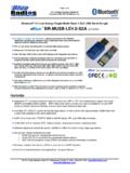
2 The is identical to the with the exception of a USB controller replacing the I2C of the S3. In addition, the S2 provides a higher maximum output power. FEATURES Integrated command stack for external control via UART or RF, with master/slave support and serial (BRSP) and battery (BAS) profiles. BRSP allows the user to stream data over LE similar to the way SPP works on Classic Bluetooth devices, but at a much lower maximum data rate. Available SDK for custom embedded applications on the module with approximately 130kB Flash and RAM available to the client application. UART (2 or 4 wire with CTS/RTS, 9600 to baud), SPI, and USB data interfaces. 12-Bit ADC with 8 channels, RTC, battery monitor, temperature sensor, watchdog timer. Software adjustable transmitter power (-23dBm to 4dBm) for short to long range applications. Very low power consumption: 27mA 0dB TX, RX down to , .9uA sleep w/timer, and deep sleep. Compatible with TI TPS62730 step down converter which can extend battery life by up to 20%.
3 Secure and robust communication link: FHSS (Frequency Hopping Spread Spectrum) 24-bit CRC Error correction for guaranteed packet delivery AES-128 bit encryption using CCM for encryption and authentication of packets. Firmware updates Over-the-Air (OTA) or over two wire UART interface. Modules easily configured to advertise as iBeacons to support immediate, near, and far proximity ranges. Free iOS & Android libraries and applications. Page 2 of 7 nBlue Module Summary Datasheet Copyright 2002-2014 BlueRadios, Inc. 8310 S. Valley Highway, Suite 275 Englewood, CO 80112 USA (303)-957-1003 FIRMWARE OPTIONS 1. Command Set for external control via UART or RF. 2. SDK for custom embedded applications, which requires the IAR Systems Compiler. APPLICATIONS - Telemedicine / Telehealth - Medical Patient Monitoring - Human Interface Devices (Keyboard, Mouse, Remote control) - Sports and leisure equipment - Mobile phone accessories - Remote controls - Consumer Electronics - Remote monitoring and control - Health Care and Medical - Smart Grid - Automated Meter Reading (AMR) - Home/Building Automation - Machine-to-Machine (M2M) - Wireless Sensor Networks - Wireless Alarms and Security - Lighting and HVAC control - Proximity and out of range detection (iBeacon)LOW ENERGY VS CLASSIC Bluetooth - Broadcast support - Connectionless always off technology - Proximity and out of range detection - 10 msec.
4 Connect time and low data latency - First low power wireless technology standard Bluetooth Low Energy, part of Bluetooth Ver. , specifies two types of implementation: single mode and dual mode. Single mode chips implement the low energy specification and consume just a fraction of the power of classic Bluetooth , allowing the short-range wireless standard to extend to coin cell battery applications for the first time. Dual mode chips combine low energy with the power of classic Bluetooth and are likely to become a de facto feature in almost all new Bluetooth enabled cellular phones and computers. Single mode Bluetooth Low Energy is NOT backwards compatible with previous Bluetooth standards. Dual mode Bluetooth Low Energy is backwards compatible but is not practical for low power devices but targeted to gateway products. An nBlue single mode module communicating over BLE once a second consumes ~30 A on average. To put this in perspective, 30 A corresponds to 330 days of battery life using a CR2032 coin cell.
5 BLE is not recommended for data streaming applications but is ideal for efficient short (20 byte or less) packet bursts. In LE, GAP defines four specific roles: Broadcaster, Observer, Peripheral, and Central. A device may support multiple LE GAP roles provided that the underlying Controller supports those roles or role combinations. However, only one LE GAP role may be supported at a given time. The Broadcaster role is optimized for transmitter only applications. Devices supporting the broadcaster role use advertising to broadcast data. The broadcaster role does not support connections. The Observer role is optimized for receiver only applications. Devices supporting the observer role are the complementary device for a broadcaster and receives broadcast data contained in advertisements. The observer role does not support connections. The Peripheral role is optimized for devices that support a single connection and are less complex than central devices.
6 Devices supporting the peripheral role only require Controllers that support the Controller s slave role. The Central role supports multiple connections and is the initiator for all connections with devices in the peripheral role. Devices supporting the central role require a Controller that supports the Controller s master role and generally supports more complex functions compared to the other LE GAP roles. Page 3 of 7 nBlue Module Summary Datasheet Copyright 2002-2014 BlueRadios, Inc. 8310 S. Valley Highway, Suite 275 Englewood, CO 80112 USA (303)-957-1003 SPECIFICATIONS SUMMARY Operating Conditions Summary Item Specifications Supply voltage (VDD) V VDD ripple 100 mV Max Max voltage on any pin VDD + .3 V (Not 5V Tolerant) Ambient Temperature Range -40 85 C Current Consumption Summary Measurements done at TA = 25 C, VDD = 3 V Item Specifications Specifications w/ TPS62730 Power Mode 3 (120 s Wake-Up) A A Power Mode 2 (120 s Wake-Up) A A Power Mode 1 (4 s Wake-Up) 235 A 235 A Low MCU Activity mA mA RX Standard Gain mA mA RX High Gain mA mA TX -23 dBm mA mA TX -6 dBm mA mA TX 0 dBm 27 mA 21 mA TX 4 dBm mA mA RF Specifications Summary Item Specifications Frequency 2402 2480 MHz in 2 Mhz steps Data Rate and Modulation 1 Mbps, GFSK Number of Channels 40.
7 37 data / 3 advertising (0,12,39) Receive Sensitivity (w/chip antenna) -95/-89 dBm Output Power -23 to 4 dBm Link Budget Up to 99dB RX/TX Turnaround 150 us Page 4 of 7 nBlue Module Summary Datasheet Copyright 2002-2014 BlueRadios, Inc. 8310 S. Valley Highway, Suite 275 Englewood, CO 80112 USA (303)-957-1003 DIMENSIONS (Without Antenna, SMD Output) x x mm (With 2 dBi TDK ANT8030-2R4-01 Antenna) x x mm Units: mm Page 5 of 7 nBlue Module Summary Datasheet Copyright 2002-2014 BlueRadios, Inc. 8310 S. Valley Highway, Suite 275 Englewood, CO 80112 USA (303)-957-1003 STANDARD LAND DIMENSIONS (WITH ANTENNA) Note: Radio requires a RF ground plane on the rest of the Printed Circuit Board (PCB) area. This can be located on any layer of the PCB. Extend the RF ground plane parallel to module pins 31 and 32 the entire length of your board.
8 Connect all ground pins and do not notch the ground plane around the module. Bottom of module is grounded so be careful of vias or conductive traces located under the modules that are not soldered masked to prevent shorting. Keep metallic components, connectors, copper traces, internal layers, and ground planes away from the antenna area in 3D space! Page 6 of 7 nBlue Module Summary Datasheet Copyright 2002-2014 BlueRadios, Inc. 8310 S. Valley Highway, Suite 275 Englewood, CO 80112 USA (303)-957-1003 PINOUT Pin Pin Name Pin Pin Name 1 GND 17 USB_DP 2 NC 18 USB_DM 3 RESET (Active Low) 19 PIO_14 4 ADC_1 20 GND 5 SPI_MISO 21 ADC_0 6 SPI_CSB 22 PIO_9 7 SPI_CLK 23 PIO_2 (20mA) 8 SPI_MOSI 24 PIO_5 (20mA) 9 VDD ( )
9 25 PIO_6 10 GND 26 PIO_3 11 UART_CTS 27 PIO_8 12 UART_RTS 28 PIO_4 (DD) 13 UART_TX 29 PIO_7 (DC) 14 UART_RX 30 GND 15 USB_VBUS 31 NC (RF Test Antenna) 16 USB_GND 32 NC (RF Test Ground) DEBUGGING PIO_4 and PIO_7 also function as the Debug Data (DD) and Debug Clock (DC) lines, allowing the modules to be connected to a TI CC-Debugger for debugging and programming.
10 See the CC Debugger User s Guide for more information: An nBlue Interace Board (IB) is also available and allows the user to debug, program, update firmware and have UART communications with any of the nBlue modules through a single or double row 10 pin header. See the nBlue Module User s Guide for more information. A CC-DEBUGGER is only needed for writing a custom application for a module and not using the command set, firmware can be updated without a debugger. Page 7 of 7 nBlue Module Summary Datasheet Copyright 2002-2014 BlueRadios, Inc. 8310 S. Valley Highway, Suite 275 Englewood, CO 80112 USA (303)-957-1003 ORDERING INFORMATION Pricing and ordering information can be found at: PART NUMBER # BR = BlueRadios LE = Low Energy = Bluetooth LE version S = Single Mode 2 = Class 1 SoC Module +150 meter (CC2540) # = A (Antenna) # = U ( RF Connector) built to order, not a stock item, 5K minimum # = N (No Antenna, SMD Output) built to order, not a stock item, 5K minimum Part Number Description 1.