Transcription of Boiling Water Reactor (BWR) Systems - nrc.gov
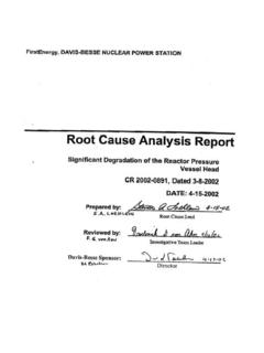
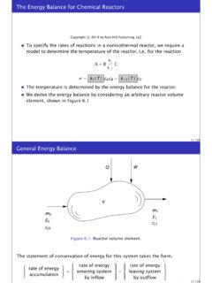
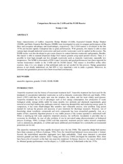
1 Reactor Concepts ManualBoiling Water Reactor SystemsUSNRC Technical Training Center3-10400 BoilingWaterReactor (BWR) SystemsThis chapter will discuss the purposes of some of the major Systems and components associated witha Boiling Water Reactor (BWR) in the generation of electrical Concepts ManualBoiling Water Reactor SystemsUSNRC Technical Training Center3-20400 Jet PumpReactorVesselSteamLineSteam Dryer&MoistureSeparatorReactor CoreRecirculationPumpThrottleValveElectr icalGeneratorTurbineCondenserPumpContain ment Suppression ChamberTurbine BuildingTo/FromRiverContainment/DrywellB oiling Water Reactor PlantInside the Boiling Water Reactor (BWR) vessel, a steam Water mixture is produced when very pure Water ( Reactor coolant) moves upward through the core absorbing heat.
2 The major difference in the operationof a BWR from other nuclear Systems is the steam void formation in the core. The steam- Water mixtureleaves the top of the core and enters the two stages of moisture separation, where Water droplets areremoved before the steam is allowed to enter the steam line. The steam line, in turn, directs the steamto the main turbine causing it to turn the turbine and the attached electrical generator. The unused steamis exhausted to the condenser where it is condensed into Water . The resulting Water is pumped out ofthe condenser with a series of pumps and back to the Reactor vessel.
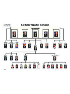
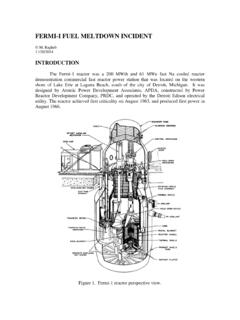
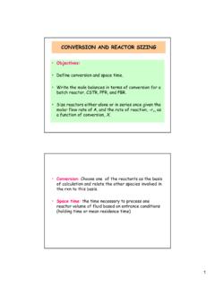
3 The recirculation pumps and jetpumps allow the operator to vary coolant flow through the core and change Reactor Concepts ManualBoiling Water Reactor SystemsUSNRC Technical Training Center3-30400 BWR Reactor Vessel AssemblyThe Reactor vessel assembly, shown on page 3-4, consists of the Reactor vessel and its internalcomponents, including the core support structures, core shroud, moisture removal equipment, and jetpump assemblies. The purposes of the Reactor vessel assembly are to: House the Reactor core, Serve as part of the Reactor coolant pressure boundary, Support and align the fuel and control rods, Provide a flow path for circulation of coolant past the fuel, Remove moisture from the steam exiting the core, and Provide a refloodable volume for a loss of coolant Reactor vessel is vertically mounted within the drywell and consists of a cylindrical shell with anintegral rounded bottom head.
4 The top head is also rounded in shape but is removable via the stud andnut arrangement to facilitate refueling operations. The vessel assembly is supported by the vesselsupport skirt (20) which is mounted to the Reactor vessel support internal components of the Reactor vessel are supported from the bottom head and/or vessel Reactor core is made up of fuel assemblies (15), control rods (16), and neutron monitoringinstruments (24). The structure surrounding the active core consists of a core shroud (14), core plate(17), and top guide (12). The components making up the remainder of the Reactor vessel internals arethe jet pump assemblies (13), steam separators (6), steam dryers (3), feedwater spargers (8), and corespray spargers (11).
5 The jet pump assemblies are located in the region between the core shroud and thevessel wall, submerged in Water . The jet pump assemblies are arranged in two semicircular groups often, with each group being supplied by a separate recirculation emergency core cooling Systems , penetrations number 5 and 9, and the Reactor vessel designs arecompatible to ensure that the core can be adequately cooled following a loss of Reactor coolant. Theworst case loss of coolant accident, with respect to core cooling, is a recirculation line break(penetrations number 18 and 19).
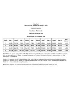
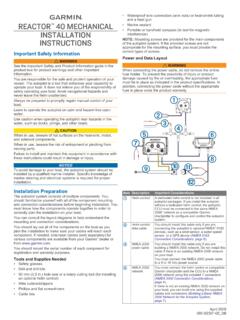
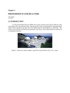
6 In this event, Reactor Water level decreases rapidly, uncovering thecore. However, several emergency core cooling Systems automatically provide makeup Water to thenuclear core within the shroud, providing core control cell assembly (page 3-5) is representative for Boiling Water Reactor 1 through 6. Each controlcell consists of a control rod (7) and four fuel assemblies that surround it. Unlike the pressurized waterreactor fuel assemblies, the Boiling Water Reactor fuel bundle is enclosed in a fuel channel (6) to directcoolant up through the fuel assembly and act as a bearing surface for the control rod.
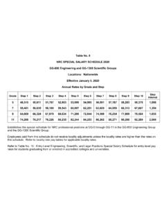
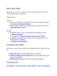
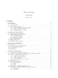
7 In addition, thefuel channel protects the fuel during refueling operations. The power of the core is regulated bymovement of bottom entry control Concepts ManualBoiling Water Reactor SystemsUSNRC Technical Training Center3-40400 BWR 6 Reactor VesselReactor Concepts ManualBoiling Water Reactor SystemsUSNRC Technical Training Center3-50400 BWR 6 Fuel AssemblyReactor Concepts ManualBoiling Water Reactor SystemsUSNRC Technical Training Center3-6 Rev 0200 SteamDryerAssem blyReactorCoreContainment/DrywellMain Steam LineMain Feedwater LineRecirculation Loop(Typical of 2)
8 RecirculationPumpContainment Suppression ChamberSteamSeparatorAssem blySafety/Relief ValveReactor WaterCleanup PumpTo Main TurbineFilter/DemineralizerReactor Building Cooling WaterNon-RegenerativeHeat ExchangerRegenerativeHeat ExchangerReactor Water Cleanup SystemThe purpose of the Reactor Water cleanup system (RWCU) is to maintain a high Reactor Water quality byremoving fission products, corrosion products, and other soluble and insoluble impurities. The reactorwater cleanup pump takes Water from the recirculation system and the vessel bottom head and pumpsthe Water through heat exchangers to cool the flow.
9 The Water is then sent through filter/demineralizersfor cleanup. After cleanup, the Water is returned to the Reactor vessel via the feedwater Concepts ManualBoiling Water Reactor SystemsUSNRC Technical Training Center3-7 Rev 0200 Jet PumpReactorVesselSteamLineSteamDryerAsse mblyReactorCoreRecirculationPumpElectric alGeneratorContainment Suppression ChamberTo/FromRiverContainment/DrywellTu rbineBypassLineService WaterResidual Heat RemovalHeat ExchangerResidual HeatRemoval PumpDecay Heat RemovalHeat is removed during normal power operation by generating steam in the Reactor vessel and then usingthat steam to generate electrical energy.
10 When the Reactor is shutdown, the core will still continue togenerate decay heat. The heat is removed by bypassing the turbine and dumping the steam directly tothe condenser. The shutdown cooling mode of the residual heat removal (RHR) system is used tocomplete the cooldown process when pressure decreases to approximately 50 psig. Water is pumpedfrom the Reactor recirculation loop through a heat exchanger and back to the Reactor via the recirculationloop. The recirculation loop is used to limit the number of penetrations into the Reactor Concepts ManualBoiling Water Reactor SystemsUSNRC Technical Training Center3-8 Rev 0200 SteamDryerAssem blyReactorCoreContainment/DrywellMain Steam LineMain Feedwater LineRecirculation Loop(Typical of 2)RecirculationPumpContainment Suppression ChamberSteamSeparatorAssem blySafety/Relief ValveRCICPumpRCICT urbineTo Main TurbineCondensateStorage TankReactor Core Isolation CoolingThe Reactor core isolation cooling (RCIC)