Transcription of Brake-Lite Relay - Roadmaster Inc.
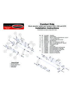
1 Installation InstructionsBrake-Lite Relaypart number 88400852701-10 , Inc. 6110 NE 127th Ave. Vancouver, WA 98682 800-669-9690 Fax: 360-735-9300 specifications are subject to change without notice Read the instructions before installing the kit components. Failure to understand how to install the Brake-Lite Relay could result in prop-erty damage, personal injury or even components Brake-Lite Relay with color-coded wiring and attachments (4) blue 16-14 gauge butt connectors and (1) ring terminal fuse tap with attached blue 16-14 gauge butt connector (1) 10-amp fuse (4) wire ties 5/16" self-tapping screw (not shown)Required tools combination wire crimper/stripper volt meter drill with 5/16" hex bitIMPORTANT NOTICE!
2 Safety Definitions These instructions contain information that is very important to know and understand. This information is provided for safety and to prevent equipment problems. To help recognize this information, observe the following symbols. WARNING indicates a potentially hazardous situation which, if not avoided, could result in property damage, serious personal injury or even death. CAUTION indicates a potentially hazardous situation which, if not avoided, may result in property damage, or minor or moderate personal used without the safety alert symbol indicates a potentially hazardous situation which, if not avoided, may result in property Refers to important information and is placed in italic type.
3 It is recommended that you take special notice of these the vehicle starts with anignition key, use the A' instructions Note: these instructions apply to the majority of vehicles. However, applications vary. Some vehicles may require ad- ditional components or alternative wiring. Note: If you are using the A' instructions, the blue wire at-tached to the Relay is not used. 1. Locate the towed vehicle s brake light switch and, with a volt meter, find the cold side of the brake light switch wire. Note: Roadmaster has identified the color of many vehicles brake light switch wires. Look under Vehicle Spe-cific Info at continued on next page Time Tested Time ProvenCAUTION Do not use the A' instructions to install the Brake-Lite Relay in a Ford vehicle with a neutral tow kit.
4 Instead, use the B' instructions (beginning on page 3). Other-wise, the neutral tow kit will not disengage the transmis-sion for towing, which may cause severe non-warranty transmission damage. Similarly, if the vehicle is equipped with a push but-ton ignition, use the B' instructions. If you use the A' instructions on a vehicle with a push button ignition, the engine will not start after the installation is from preceding page Confirm that you have found the correct wire 1) the volt meter will not register voltage unless the brakes are applied; and 2) when the brakes are applied the volt meterwill register 12 VDC+.
5 CAUTION Do not rely on a test light to identify the brake light switch wire other wires may also energize a test light. You must use a volt meter to confirm that you have found the correct wire only the brake light switch wire will register 12 VDC+ in the above test. The Brake-Lite Relay will be attached to the wire you have selected. If the Relay is attached to the incorrect wire the vehicle's cruise control, anti-lock brake sys-tem or other electronic components may be damaged or disabled, causing non-warranty damage to the vehicle's electrical system. 2. Remove the vehicle s brake light fuse, located in the fuse Failure to remove the brake light fuse from the fuse panel may cause the vehicle s theft deterrent system or other electrical system indicators to be activated ifthe brake pedal is depressed during the installation.
6 This may require non-warranty repair to the vehicle. 3. Cut the brake light wire, a few inches downstream from the cold side of the brake light switch. 4. Attach this wire and the brake monitor wire from the supplemental braking system to the brake signal output (Fig-ure 1). Note: for Even brake , connect the brake signal output to terminal 1 in the ICX transmitter. 5. With the attached blue butt connector, connect the black wire from the Brake-Lite Relay to the other end of the brake light wire (Figure 1). 6. Identify a fuse that is ONLY powered when the ignitionFigure 2 Figure 1key is in the run position and OFF when in the tow posi-tion.
7 Pull the fuse. Do not remove any fuse connected to the air bag cir-cuit. Air bag deployment can result. Consult the vehicle owner s manual to determine fuse assignments for other safety systems. Note: make certain this fuse is not part of a retained accessory power circuit with this feature, the vehicle s electronics continue to function normally for about ten min-utes after the ignition is turned off. Then the electronics willno longer function, which shuts off power to the brake light switch. Insert the fuse you just pulled into the slot closest to the fuse blades (Figure 2), then insert the fuse tap into the empty slot in the fuse panel (Figure 1).
8 Using the attached blue butt connector, connect the red wire from the Brake-Lite Relay to the wire from the fuse tap (Figure 1). 7. With the attached ring terminal and included 5/16" self-tapping screw, connect the white wire from the Brake-Lite Relay to any good chassis ground. To avoid groundingproblems, attach the wire directly to the The towed vehicle must be grounded to the motor-home. If it is not, the Brake-Lite Relay will not operate. Additionally, failure to establish a good ground be-tween the towed vehicle and motorhome could cause aftermarket accessories to malfunction, damage to both vehicle s electrical systems and other consequential damage.
9 8. Secure the Brake-Lite Relay in place, using one or more of the included wire ties. Ensure that the wiring will not present an obstacle or hazard to the driver of the vehicle, or interfere with the op-continued on next page 1. Use the B' instructions ..the vehicle is equipped with a push button ignition..you will install the Relay in a Ford vehicle with a neutral tow' kit. Note: this installation requires parts and materials which are not supplied one 12-10 gauge butt connector, one 16-14 gauge butt connector and several feet of brown 14 gauge wire. Additionally, one diode ( Roadmaster part number 790) may be required. See step 10.
10 Note: applications may vary. Some vehicles may require additional components or alternative wiring. Note: If you are using the B instructions, the green wire attached to the Relay is not used. 2. Locate the towed vehicle s brake light switch and, with a volt meter, find the cold side of the brake light switch wire. Note: Roadmaster has identified the color of many vehicles brake light switch wires. Look under Vehicle Spe-cific Info at Confirm that you have found the correct wire 1) the volt meter will not register voltage unless the brakes are applied; and 2) when the brakes are applied the volt meter will register 3 Figure 3continued from preceding pageeration of the vehicle.