Transcription of Brick Tie Design Section 2.5 - Masonry Institute of ...
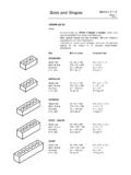
1 Brick Tie Design Section 111/05 GENERAL Brick tie requirements are outlined in CSA A370-04 Connectors for Masonry . The older kinds of ties, such as strip ties and Z ties as are seldom used in modern commercial construction, can not be used in higher seismic zones, and are now referred to as Prescriptive Ties . The newer, 2-piece, adjustable, engineered ties that are now in common use are now simply referred to as Ties . CSA A370-04 contains strict Design requirements for strength, deflection and free play. Ties are designed to resist the lateral wind and seismic loads provided for specific locations by the Building Code (BCBC). Factored Tie Capacities are normally provided by test data from the manufacturers. Corrosion resistance is a key requirement for ties which are required to secure Masonry claddings over their long expected life.
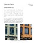
2 The Section below updates the corrosion requirements first introduced in the 1994 standard, which included the use of stainless steel ties in higher Masonry walls in regions of the country which experience high wind-driven rain conditions. STAINLESS STEEL TIES The 2006 BCBC references the 2004 edition of CSA A370, "Connectors for Masonry ". The standard requires stainless steel ties for Masonry over 13 m high (formerly buildings over 11 m) for areas subject to high wind-driven rain such as coastal Hot dipped galvanized coatings are acceptable corrosion protection for walls 13 m or lower in coastal , and for all wall heights in the drier areas of The standard provides rain data for locations across Canada in Annex E, in terms of Annual Driving Rain Indices (aDRI).
3 To take full advantage of the very long service life offered by Masonry veneers, stainless steel ties may also be specified for lower walls on institutional or monumental buildings. It may also be simpler to specify stainless steel ties for the lower walls of buildings using them on higher levels of the structure. In any case, the impact on total wall cost is relatively minor. Stainless steel ties are readily available, and have been used on many projects on the west coast for over a decade. aDRI Values in : Abbotsford * Cranbrook Kamloops Port Alberni * Prince George Prince Rupert * Vancouver * Victoria * * Locations with values above require stainless steel ties for walls over 13 m.
4 Ties must be labeled: Tie packaging or pieces must be labeled, including corrosion protection type Section Page 2 11/05 Brick Tie Design TIE Design for SEISMIC LOADS Earthquake lateral loads on Brick ties are determined by the formula for elements and components of buildings and their connections from the BCBC (clause ): Vp = Fa Sa( ) IE Sp Wp Where: Vp = lateral force Fa = acceleration based site factor (soil type) Sa( ) = spectral response acceleration (seismic factor) IE = building importance factor: ; except for schools,etc.; for post-disaster Sp = Cp Ar Ax / Rp ( < Sp< ) Cp = component factor: for ties Ar = component force amplification factor: for ties Ax = height factor: , worst case at top of wall for ties Rp = component response modification factor: for ties, for fasteners Wp = weight of component: take as kN/m2 Sp = ( )( )( ) / = ( < Sp< ) This new formula in the 2006 BCBC may result in lower lateral seismic loads that the previous code version ( Vp= , with Sp=5).
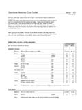
5 This may result in wind loads governing in more cases. Where IE Fa Sa( ) < , these requirements do not apply for Masonry veneer connections for buildings, other than post-disaster buildings. The latest generation of strong, 2-piece adjustable ties can provide the opportunity for spacings up to the maximum allowable of 600 mm vertically and/or 820 mm (32 ) horizontally. For metric block and metric stud spacings, the effective horizontal maximum is 800 mm. Brick Tie Design Section 311/05 Brick TIE Design EXAMPLE The structural Design example below is based upon the requirements of the 2006 BCBC; CSA Design of Masonry Structures; and CSA A370-04 Connectors for Masonry . The process begins with the calculation of seismic and wind loads for a typical 2-storey school in Vancouver.
6 The seismic case is assumed to govern for this example. For this example, we try a tie with a factored resistance ( Design strength) of kN. The allowable spacing of the ties may be affected by whether the back-up wall is concrete block or steel stud. The spacing for the non-flexible block wall is directly obtained by dividing the tie strength by the applied load in kN/m2, which results in an area in this case of m2 ( sq. ft.) per tie. However, the maximum spacing for any tie system to metric block is limited to a maximum of 600 mm by 800 mm (.48 m2) ( ), so this spacing is specified. (actual horizontal spacing maximum is 820 mm to accommodate studs at 32 in.) For the flexible steel stud back-up, additional requirements are applied to account for the less rigid support condition.
7 For this case, a smaller wall area per tie of .42 m2 ( sq. ft.) is calculated, and the spacing options are based on stud space increments. The selection of a higher capacity tie may put both back-up systems into the maximum spacing condition. PROJECT: Vancouver, 2 storey school, on soft rock Brick veneer on both concrete block, and steel stud back-up: stud spacing @ 400 mm, stud height m. 1. LATERAL LOADS Wind Load: The Factored Wind Load calculation as determined for other components at the most severe location on the building may govern for veneer ties, compared to the seismic example below. Staggered ties allowed: A370-04 now allows ties to be placed in a staggered pattern. This may be more efficient, and ensure that all studs are loaded for wood and metal backups.
8 There must be a top row tie at every stud line. Section Page 4 11/05 Brick Tie Design Seismic Load: Vp = Fa Sa( ) IE Sp Wp Fa = ; Sa( ) = ; IE = ; Wp = kN/m2 Sp = Cp Ar Ax / Rp = ( )( )( ) / = Vp = ( )( )( )( )( ) = kN/m2 2. TIE SPACING (Assume Seismic governs for this example) Examine spacing for a tie with a factored resistance of kN (from manufacturers' test data literature) Concrete Block Back-up (non-flexible) Area = kN / kN/m2 = m2 / tie - Therefore space at the maximum 600 mm vertically by 800 mm horizontally. Area = m2 - Could also consider lower capacity tie. Steel Stud Back-up (flexible) - Double tributary area load for flexible back-up: Area = kN / ( kN/m2 x 2) = m2 / tie - Check 40% of stud load: (40%)( )( )( ) = kN / tie < kN tie capacity - OK Spacing options: 1.
9 Maximum vertical spacing of 600 mm by the stud spacing of 400 mm horizontally. Area = m2 ( OK) 2. Horizontally at double stud spacing of 800 mm (staggered) by a vertical spacing of 450 mm. Area = m2 ( ) (Based on vertical Brick module fitting 450 mm.) 3. Could also consider a higher capacity tie. Note: CSA A370-04 requires a minimum unfactored tie strength of kN. Spacing at Openings and Tops & Bottoms of walls: - Openings: not more than 300mm from edge at maximum 600 mm spacing. - Top: not more than 300mm to top row, at every stud, even if staggered. - Bottom: not more than 400mm to bottom row.