Transcription of Bridge Design Guide
1 Bridge Design Guide Bridge Division January 2020 Bridge Design Guide 1- 1 TxDOT January 2020 Chapter 1 About this Guide Contents: Section 1 Introduction .. 1- 2 Chapter 1 About this Guide Section 1 Introduction Bridge Design Guide 1- 2 TxDOT January 2020 Section 1 Introduction Purpose This document presents guidelines for designing bridges in Texas. This document should be used in companion with the policies stated in the TxDOT Bridge Design Manual - LRFD. The main objectives of this document are to: Serve as a resource for engineers designing bridges for TxDOT. Provide guidelines specific to TxDOT policies, details, and Design assumptions. Updates Updates to this Guide are summarized in the following table. Guide Revision History Version Publication Date Summary of Changes 2018-1 August 2018 New Guide published. 2020-1 January 2020 Chapter 3: Additional Section 12, System Redundancy Evaluation for Steel Twin Tub Girders added to Guide . Appendix C, Steel Twin Tub Girder System Redundancy Simplified Method Guide , added.
2 Organization The information in this Guide is organized as follows: Chapter 1, About this Guide Chapter 2, Load and Resistance Factor Design Chapter 3, Superstructure Design Guidelines Chapter 4, Substructure Design Guidelines Chapter 5, Other Design Guidance Chapter 6, Frequently Asked Questions Appendix A, Pretensioned concrete TxGirder Haunch Design Guide Appendix B, Pretensioned concrete U Beam Design Guide Appendix C, Steel Twin Tub Girder System Redundancy Simplified Method Guide Chapter 1 About this Guide Section 1 Introduction Bridge Design Guide 1- 3 TxDOT January 2020 Feedback For TxDOT policy on designing bridges, please refer to the TxDOT Bridge Design Manual - LRFD. Please direct any questions on the content of this document to the Bridge Design Section Director, Bridge Division, Texas Department of Transportation. Bridge Design Guide 2- 1 TxDOT January 2020 Chapter 2 Load and Resistance Factor Design Contents: Section 1 Load Factors .. 2- 2 Chapter 2 Load and Resistance Factor Design Section 1 Load Factors Bridge Design Guide 2- 2 TxDOT January 2020 Section 1 Load Factors Load and Resistance Factor Design Load and Resistance Factor Design (LFRD) is a methodology that makes use of load factors and resistance factors based on the known variability of applied loads and material properties.
3 Bracketed <references> reference relevant sections of the AASHTO LRFD Bridge Design Specifications. Load Factors TxDOT recommends the following load factors from <Article >: The engineer may reduce the maximum load factor for wearing surfaces and utilities <DW in Table > to Chapter 3 Superstructure Design Guidelines Section 1 General Recommendations Bridge Design Guide 3- 1 TxDOT January 2020 Chapter 3 Superstructure Design Guidelines Contents: Section 1 General Recommendations .. 3- 2 Section 2 Superstructure Phasing Guidance .. 3- 4 Section 3 Corrosion Protection Measures .. 3- 10 Section 4 concrete Deck Slab on Stringers .. 3- 11 Section 5 concrete Deck Slab on U Beams .. 3- 13 Section 6 Pretensioned concrete I Girders .. 3- 14 Section 7 Pretensioned concrete U Beams .. 3- 16 Section 8 Pretensioned concrete Slab Beams and Decked Slab Beams .. 3- 18 Section 9 Pretensioned concrete Box Beams .. 3- 19 Section 10 Straight and Curved Plate Girders.
4 3- 21 Section 11 Spliced Precast Girders .. 3- 22 Section 12 System Redundancy Evaluation for Steel Twin Tub Girders .. 3- 23 Chapter 3 Superstructure Design Guidelines Section 1 General Recommendations Bridge Design Guide 3- 2 TxDOT January 2020 Section 1 General Recommendations prestressed concrete Beam and Girder Design TxDOT s policy is held firmly to a ksi maximum allowable concrete strength (f ci) at time of release of prestressing tension. The most severe Alkali Silica Reaction (ASR) and Delayed Ettringite Formation (DEF) problems in Texas have been in precast members. Texas has some of the most highly reactive aggregates in the country. For prestressed concrete , fabricators often use high cement contents to gain early strength, which means more alkalis. Large amounts of reactive silica plus large amounts of alkali equal higher ASR potential. The Class F fly ash typically used in our prestressed concrete helps mitigate these issues, but with the decreasing availability of fly ash and changing fly ash chemistry, ASR may still be an issue.
5 Incidents of ASR have caused TxDOT to revisit mix designs and the attainable concrete strengths used in the fabrication of prestressed concrete products. Item 421, Hydraulic Cement concrete , requires fly ash or other combinations of supplementary cementing materials to be used in all beam production. This will result in slower strength gains which could have a negative impact on fabricator production and ultimately on girder costs. In order for fabricators to achieve higher early age concrete strengths with these slower strength gaining mixes, use of additional cement is often added. The other issue that occurs in prestressed concrete is the use of low water-to-cementitious ratios (w/cm). Autogenous shrinkage and other problems related to the low w/cm ratios have increasingly become an issue in precast plants to the point that TxDOT put a limit on how low the fabricator can set the w/cm ratio. TxDOT has seen a large amount of early age cracking in prestressed girders that is now believed to be caused by high cement contents and very low w/cm ratios.
6 Specifying release strengths above the ksi limit encourages the use of higher cement contents, which increases the likelihood of premature concrete deterioration. Low cement content has numerous benefits such as lower shrinkage and heat of hydration generation. Again, Texas is a unique case because essentially all our aggregate deposits are reactive. For this reason, these additional steps are necessary to ensure good long term durability and performance. As stated in the policy manual, TxDOT Bridge Design Manual - LRFD, limit concrete strength at time of release of prestressing tension, f'ci, to a maximum of ksi. Design concrete strength, f'c, is limited to a maximum of ksi. The following links are provided for additional reading on ASR: Preventing Alkali-Silica Reaction and Delayed Ettringite Formation in New concrete Chapter 3 Superstructure Design Guidelines Section 1 General Recommendations Bridge Design Guide 3- 3 TxDOT January 2020 Guidelines for the Use of Lithium to Mitigate or Prevent Alkali-Silica Reaction (ASR) Chapter 3 Superstructure Design Guidelines Section 2 Superstructure Phasing Guidance Bridge Design Guide 3- 4 TxDOT January 2020 Section 2 Superstructure Phasing Guidance Phased Construction Recommendations Do not use span standard detail sheets for phased structures.
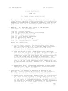
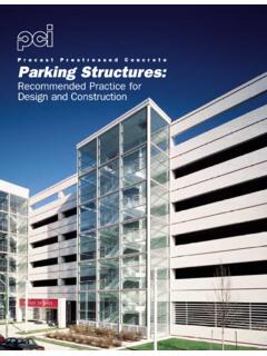
7 In other words, for a 38 ft. roadway phased Bridge , do not use the 38 ft. roadway standards. Geometric Constraints When selecting a location for the phase line, consider the following items: Traffic needs and the placement of any temporary barriers. If the clear distance between the back of the barrier and the edge of the slab is less than 2 feet, pin the barrier to the deck. If possible, allow a 2 ft. buffer when placing the temporary barrier on new Bridge deck to avoid the need for installing pins in the new Bridge deck. When building next to an existing structure (such as for phased replacements), provide enough space between the existing structure and the new construction to accommodate splicing of the deck reinforcement, the portion of the beam that extends beyond the edge of slab, the portion of bent or abutment that extends past the beam edge, any reinforcing of the bent or abutment that extends into the next phase, and form work. For TxGirders, place the phase line as shown in Figure 3-1.
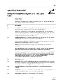
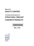
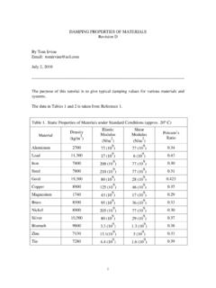
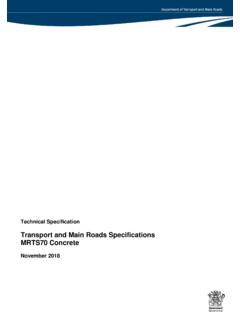
8 1. Do not place a phase line in the middle or at the edge of a precast panel as shown in Figure 3-6. 2. Do not place the phase line closer than 7 1/2 inches from the beam edge, to allow for the use of precast panels in the future phase. 3. Place the phase line a minimum of 4 inches past the centerline of the girder, so that the horizontal interface reinforcement is cast into the initial construction phase of the slab. 4. Alternately, consider placing the phase line between two beams. Treat the slab between the beam and the phase line as an overhang. Do not allow the use of panels in this space. For adjacent slab or box beam superstructures, place the phase line at the edge of the beam, as shown in Figure 3-2 and Figure 3-3. Do not place a phase line within the top flange of a Slab Beam or adjacent Box Beam as shown in Figure 3-7. For U-beam and X-Beams, place the phase line as shown in Figure 3-4 and Figure 3-5. 1. Place the phase line along the top flange of the beam.
9 If the phase line is located along the top flange of the beam, the majority of the beam will be under the initial phase of construction. Chapter 3 Superstructure Design Guidelines Section 2 Superstructure Phasing Guidance Bridge Design Guide 3- 5 TxDOT January 2020 2. Do not place the phase line closer than 6 1/2 inches from the beam edge for U-beams and 10 inches for X-Beams, to allow for the use of precast panels in the future phase. 3. Alternately, consider placing the phase line between two beams. Treat the slab between the beam and the phase line as an overhang. Do not allow the use of panels in this space. If a full depth open longitudinal joint is used at the phase line, the Bridge is considered 2 structures and should have 2 NBI numbers. Phased superstructures may require variable spacing of beams. Load rating of the existing structure is required if the phasing scheme removes portions of the existing structure. Acceptable load rating limits for phased construction of existing structures should be discussed with the District where the work is performed.
10 Figure 3-1: Phasing for TxGirders Chapter 3 Superstructure Design Guidelines Section 2 Superstructure Phasing Guidance Bridge Design Guide 3- 6 TxDOT January 2020 Figure 3-2: Phasing for Slab Beams Figure 3-3: Phasing for Box Beams Figure 3-4: Phasing for U Beams Chapter 3 Superstructure Design Guidelines Section 2 Superstructure Phasing Guidance Bridge Design Guide 3- 7 TxDOT January 2020 Figure 3-5: Phasing for X-Beams Chapter 3 Superstructure Design Guidelines Section 2 Superstructure Phasing Guidance Bridge Design Guide 3- 8 TxDOT January 2020 Figure 3-6: Incorrect Phase Joint Location Examples Figure 3-7: Incorrect Phase Joint Location Examples Structural Analysis When designing the beams, consider all temporary loading such as temporary rails as permanent loads for that phase. Design beams so that they meet all requirements for all phases of construction. Chapter 3 Superstructure Design Guidelines Section 2 Superstructure Phasing Guidance Bridge Design Guide 3- 9 TxDOT January 2020 The beam located under the phase line will have less dead load deflection than the other beams constructed at the same time.